FCC ID:SY4-A02032 APACHE 3 User Guide Marine Survey | Jul 2021 APACHE 3 User Guide (Network Bridge Version)| 2021-07 Pa ge |1
Table of Contents Copyright.................................................................................................................................4 Safety Warnings...................................................................................................................... 4 FCC Interference Statement....................................................................................................4 CE Interference Statement.................................................................
.3.2. Register the receiver...............................................................................................21 3.3.3. Configure the I/O of rover station.......................................................................... 21 3.3.4 System State............................................................................................................ 22 3.3.5 Firmware upgrade....................................................................................................23 3.
Preface Copyright Copyright 2016-2017 CHC | Shanghai Huace Navigation Technology Ltd. All rights reserved. The CHC are trademark of Shanghai Huace Navigation Technology Limited. All other trademarks are the property of their respective owners. Trademarks All product and brand names mentioned in this publication are trademarks of their respective holders. Safety Warnings The Global Positioning System (GPS) is operated by the U.S.
Introduction The APACHE 3 USV User Guide describes how to set up and use the CHC® APACHE 3 USV. In this manual, “the USV” refers to the APACHE 3 USV unless otherwise stated. Even if you have used other Unmanned Surface Vessel before, CHC recommends that you spend some time reading this manual to learn about the special features of this product. If you are not familiar with USV, go to www.chcnav.
receiver(s). If you need to contact CHC technical support, please contact us by email (support@chcnav.com) or Skype (chc_support). Disclaimer Before using the receiver, please make sure that you have read and understood this User Guide, as well as the safety information. CHC holds no responsibility for the wrong operation by users and for the losses incurred by the wrong understanding about this User Guide. However, CHC reserves the rights to update and optimize the contents in this guide regularly.
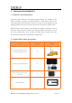
1 Getting Started with APACHE 3 1.1 APACHE 3 brief introduction Featuring triple-hulled and the shallow draught design, the APACHE 3 USV offers a portable remotely controlled platform in small lakes, inland rivers, and coastal water for bathymetric surveys. Its overall 1-meter length and 7 kg weight (without instrument) allows one person to operate the system easily. Multiple data transfer options are available with RS232 connection and TCP protocols along with multi-channel and high bandwidth transmission.
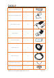
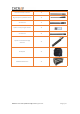
LiPo Battery (40000mAh 18V) 4 LiPo Battery (15000mAh 18V) 1 Lithium Battery Charger 3 Hand Toolbox 1 5.
Remote Control Antenna 1 High Frequency Radio Antenna 1 4G Antenna 1 Hydro Survey Dongle Version 1 5G Antenna 3 Tripod For Network bridge Antenna 1 Backpack 1 APACHE3 Hard Case 1 APACHE 3 User Guide (Network Bridge Version)| 2021-02 Page|9
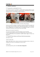
2 Hardware Installation 2.1 Preparing for conducting the survey It is necessary to have an accumulator to supply power for external radio if you use external radio mode. Full charge the remote controller and batteries with standard charwger. Figure 2-1 is about how to charge the batteries. Figure 2-1 and 2-2 Battery connection during charging Firstly we connect the charger to the battery interface, pay attention to tighten the nut, and then connect to 220v AC power supply.
Figure 2-3 Set RTK Base Station Check the accuracy of the rover station: Under the fixed solution state, compare the accuracy of the RTK rover station with the coordinates of the known points to ensure that the accuracy meets the measurement requirements before proceeding to the next operation. 2.3 Install Accessories for the USV System 2.3.
Figure 2-5 Connect battery-powered interface Note: Two large batteries are placed in the boat. Pay attention to the direction when installing the battery power detection interface. 2.3.2 Mount the accessories of the ground station Figure 2-6 Working with backpack Figure 2-7 Working with tripod 2.3.3 Debug before launching the boat 1). Boot the boat Turn on the switches on both sides of the boat.
Figure 2-8 Remote control 3). Debug the motors Use the remote control to check whether the motors are working properly.
3 Software Operation for the USV System 3.1 Install the software There are two software for the USV system, AutoPlanner and HydroSurvey. 1) When installing the AutoPlanner software, double-click the installation package, click Next until the installation driver and plug-in interface appears, tick ‘Install Tap Driver’ and ‘Install Ezopen Plugin’, and then click Next until the installation is OK.
Figure 3-3 Configure the computer IP 3.2.2 TCP Connection for AP Software Double-click the AP software icon to open it, select [TCP], and click [Connect]. Figure 3-4 TCP connection 3.2.3 Plan Route for AP Software (1)Connect the computer to the network, and load the surrounding satellite image maps through the positioning of the boat. Select [NAVIGATION PLAN] on the main interface, and select the appropriate satellite image map. Commonly used are Bing satellite maps and Google satellite maps.
(2)Plan work area Right-click on the interface and select [Draw Polygon] → [Add Polygon Point]. Note: 1) The satellite image is not updated in real time, so pay attention to the actual area when planning the polygon. 2) The role of the home point: a. The home point is the return point. b. The logic for generating the automatic route is to generate the waypoint 1 near the home point, and the other waypoints are generated in sequence.
(3)Edit auto waypoints Right click the interface and select [Auto WP] [WP Grid]. Figure 3-7 Set WP Grid Figure 3-8 Set WP Grid [Angle]: Adjust the angle of the route. [Distance between lines]: The distance between routes. [Spacing inline]: The distance between points on the route, the value set should be greater than the true distance of the route, so as to ensure that there are only two points on a route. The automatic waypoint spacing here is not the same as the data collection spacing.
[Save WP File]: Save the currently planned route to computer. [Load WP File]: Load the WP file from computer. [Read WP File]: Read the current mission waypoints from boat. [Write WP File]: Write the planned waypoints data to the central control. Figure 3-9 Write WP into boat 3.2.4 Login HD Camera for AP Software a. Click [Navigation Data][Spread/Shrink Hud and Video][Intranet] Username: admin Password: Admin1234 IP: 192.168.53.64 Port: 8000 b.
Figure 3-11 Login HD camera 3.2.5 Other common functions for AP Software 1. Control USV via AP software Click [Shrink Remote-Control], remotely control USV by dragging the blue dot. Figure 3-12 Control USV via AP software 2. Useful functions [Set WP]: Set a new waypoint quickly without clicking the navigation plan interface. [Restart mission]:back to the first point and start a new mission. [Clear track]:clear the track line of the interface you have run. [Keep loiter]:change the state of the boat.
Figure 3-13 Other functions 3. Convenient switch Now we can turn on the switch when you need in software instead of Web page. shoal: set a shoal depth to ensure your boat's safety. avoid obstacles: set a distance to ensure your boat will not crash into some objects in water. low power return: makes you boat return to home point automatically. lost connection and return: makes you boat return to home point automatically when your boat has lost connection for few times. Figure 3-14 Convenient switch 3.
Username: admin Password: Admin1234 Figure 3-15 login webpage of the GD100 3.3.2. Register the receiver Click [Firmware][GNSS Registration]. Send the receiver SN to the dealer or sales branch to obtain the registration code. Enter and apply the correct registration code. Figure 3-16 Register the receiver 3.3.3. Configure the I/O of rover station There are two kinds of working modes for rover station: 1) CORS mode. 2) Internal radio mode 1. Set CORS mode. Click [I/O Setting][RTK Client][Connect].
Figure 3-17 Set CORS mode 2. Set internal radio mode. [System Setup][Radio Settings] Figure 3-18 Set internal radio mode 3.3.4 System State Click [Unmanned Ship Status][System State] The status of USV, positioning status, battery status, sounder status, etc. can be viewed in this Interface.
Figure 3-19 System state 3.3.5 Firmware upgrade We have updated the firmware frequently, you can upgrade the control firmware, host firmware and Echo Sounder control firmware when you need.
3.4 Set Hydrosurvey 3.4.1 New project and connect to the boat 1)Open HydroSurvey 7 , click on [Project] - [New Project]. "Project name"is default and can be renamed if you need. And it also can be saved as a template via clicking [Save coord template]. It is important to input the deviation if you perform the base shift. Figure 3-21 Create a new project and set coordinate system 2) click to connect the GPS and the sounder after you have connected the boat via AutoPlanner.
Figure 3-22 Main interface 3.4.2 Record control As shown in the following figure 3-27, click on [Setting] – [Record control]. If [By Distance] is set to 1 M, a point will be recorded for every meter; if [By Time] is set to 1 S, a point will be recorded for every second; if [By Space] is ticked, a point will be recorded once you click the space bar. In terms of Limitation selection, [Fixed] is recommended when RTK is used and [Float] is recommended when beacon is used.
3.4.3 start work When the new projects, parameters, data, settings and other preparations are done well, data can be recorded. ①Choose [measure mode] ② Toolbar indicates the start, pause, and stop the record. Meantime, line name could be entered at the beginning of measuring. ③In order to facilitate post processing and prevent massive loss of data in unexpected cases, it is suggested to change a line every 300 or 500 points.
3.4.4 Download depth file from boat(skip this step if you need not) 1. connect the wifi of boat(serial number of the boat) Figure 3-25 Connect wifi Open a file maybe 'This PC'on your computer, and input IP:ftp://192.168.53.
3. Username: admin Password: Admin1234 Figure 3-27 Input username and password 4. copy the files from record2 file dep files record the original data. Sd files record the waveform.
5.
4 Data Processing 4.1 Water depth sampling Water depth sampling is a process that correct the depth data and handle the wrong depth data. We will get a htt file including all data that can be select in the data export section after sampling. This process will be divided into four steps. 1.Correct the depth via sound velocity correction tick [All], select [Correct] to get the edit interface.
As the figure 4-2 shows, there are three ways to correct the sound velocity: Single Sound velocity, Depth +Sound velocity, Depth+ Correction. Take the second method as an example (1) Import the sound velocity file via clicking [Import] button, the format should be as follows: Figure 4-3 Sound velocity file The first column is depth, and the second one is the sound velocity. (2) the imported sound velocity will be shown in the list.
(3) Calculate correction and apply it to all raw data. Click [Correct] button, then it will pop up successfully applying information Figure 4-4 Apply sound velocity file (4) Skip Delay correct and attitude correct The delay correct is the correction for GPS and depth transmission delay. The impact of time delay on bathymetric data can be reduced. The time delay value for the whole system is a fixed. Enter a known time delay value or calculate it via a special method if necessary.
2. Handle the depth data Double click a depth file in the depth file list. Figure 4-6 Depth sampling interface As the figure 4-6 shows, the green line on the top of main interface shows the elevation of surface of water and fixed state (yellow represent floating and red represent a single point), the main interface can be changed by adjusting the [Depth H]and [Width]. the green line displayed on the bottom interface shows depth, the red line is simulative echo signal.
Figure 4-7 Interval setting 4. You also can change the interval via clicking [Manual] button. Figure 4-8 Manually change interval 5. Click [4.Export htt] When the interval setting is complete, click [4.
Figure 4-9 Export htt files 4.2 Data export Click on [Data processing] – [Data Export], Select the Htt files and choose a file type, there are some default format for option, and the format also can be modified via [Customer]. At last export data to desktop via clicking [ Export].
Figure 4-11 Data export Select the [Save Path] and click on [Export], the final result will be acquired.
1) FCC 15.19 This device complies with part 15 of the FCC Rules. Operation is subject to the following two conditions: (1) This device may not cause harmful interference, and (2) this device must accept any interference received, including interference that may cause undesired operation. 2)FCC 15.21 Warning: Changes or modifications to this unit not expressly approved by the part responsible for compliance could void the user’s authority to operate the equipment. 3) FCC 15.
CHC Navigation Building D, NO. 599 Gaojing Road, Qingpu District, 201702 Shanghai, China Tel: +86 21 542 60 273 | Fax: +86 21 649 50 963 Email: sales@chcnav.com | support@chcnav.com Skype: chcnav_support Website: www.chcnav.