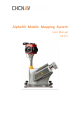
Alpha3D Mobile Mapping System User Manual V1.0.
Table of Content Table of Content Table of Content............................................................................................................... 2 1 Reading Tips .............................................................................................................. 5 1.1 Symbol Explanation .................................................................................................. 5 1.2 Recommendation ............................................................................
Table of Content 5 4.1.2 Orange Container Port .............................................................................. 30 4.1.3 Controller Box Port .................................................................................... 31 4.2 Functional Specification ......................................................................................... 33 4.2.1 Orange Container Function ....................................................................... 33 4.2.1.
Table of Content 6 7 5.2.2.2 Base Data Processing ......................................................................... 65 5.2.2.3 License Activation .............................................................................. 67 5.2.2.4 Data Format Conversion .................................................................... 68 5.2.2.5 POS Processing................................................................................... 69 5.2.2.6 GPS/INS Combine Processing ..........................
Reading Tips 1 Reading Tips 1.1 Symbol Explanation : Forbid : Warning : Important attention : Instruction 1.2 Recommendation CHCNAV provides follow documents for user: ◼ ◼ Items List Alpha3D Mobile Mapping User Manual The above content is recommended for user to read carefully before first-time use. 1.3 Service & Support CHCNAV website: http://www.chcnav.
Reading Tips 1.4 Disclaimer ◼ ◼ ◼ ◼ ◼ Client needs to use and maintain the instrument as per CHCNAV requirements. If the instrument’s life is affected even broken because of customer’s incorrect operation & maintenance, CHCNAV will not assume the relevant responsibilities and all maintenance services will be charged at standard rates. Client needs to provide stable vehicle roof rack based on special technical parameters.
User Guide 2 User Guide 2.1 Operation Environment ◼ ◼ ◼ ◼ Not recommend using on rainy day, snowy day and foggy day for security and more noise points reasons. Not recommend using on a dusty environment as it will reduce instrument’s lifetime. Do not put instrument and accessories under extreme temperature. The environment temperature should not lower or higher than specific temperature.
User Guide ◼ Check whether the indicator light of Ladybug camera is orange after powered on. 2.4 Attentions After Using ◼ ◼ ◼ After work finished, turn off laser on CoCapture first, then turn off battery and remove power cable. Finally put instrument and all accessories into case. Please move case carefully during transit and do not bump. The battery box should be turn off.
Product Overview 3 Product Overview 3.1 Product Introduction The Alpha3D is an advanced mobile mapping system which completely designed and integrated by CHC Navigation Company. It combines several state-of-the-art high-performance sensors, for example 3D laser scanning module, satellite positioning module, inertial navigation module and 360°HD panoramic camera.
Product Overview 3.2 Product Component 3.2.
Product Overview 1904 110 014 Inertial Explorer 1yr CSP 1 1904 110 664 CoCapture license 1 1904 110 015 CoCapture 1yr CSP 1 1904 110 662 CoPre license 1 1904 110 016 CoPre 1yr CSP 1 1904 110 660 CoProcess license-(better $12500) 1 1904 110 017 CoProcess 1yr CSP 1 1904 110 666 CoSurvey AutoCAD license-(better $6250) 1 1904 110 018 CoSurvey AutoCAD 1yr CSP 1 1904 110 668 CoManager GIS license 1 1904 110 019 CoManager GIS 1yr CSP 1 1904 110 667 CoView (Panoramic publishing pl
Product Overview 3.2.
Product Overview ① ② ③ ④ ⑤ ⑥ Roof rack extension: Fixed on the car roof for installation of instrument; USB stick: Used to store initial parameters and product manual; Instrument: Used for data capture and storage; Accessories cables: Power cable, VGA cable, data line etc; Displayer cable: Used for connection between instrument and displayer; Displayer: Used for test and recondition. 3.2.
Product Overview 3.3 Product Details 3.3.1 Alpha3D Hardware ◼ Main instrument: Used for data capture and data storage. ◼ Power cable: Used for main instrument charged. The output interface is 1B Lemo fourcore aerial plug which mainly used for indoor testing. The input voltage of power adapter is 100-240VAC, output voltage is 24V and maximum power is 221W. ◼ Antenna: Used to receive satellite signal for GPS timing.
Product Overview ◼ GNSS cable: Used for connection between antenna and instrument. ◼ Portable displayer kit: Used for indoor test and recondition. ◼ Wireless keyboard: Used for software operation and parameter configuration. ◼ Data line: One internet access and two USB interfaces which are 1B 17-core aerial plug.
Product Overview ◼ VGA video line: One side connect to displayer and another 1B 10-core Lemo aerial plug connect to DISP interface. ◼ Battery power cable: One side is 1B 4-core aerial plug with needle which connect to battery power; Another side is 1B 4-core aerial plug with hole which connect to DC24V interface. ◼ Hardware operation interface: ON/OFF: Button to control switch on/off with green light. CAMERA: External camera interface. EXT1: Firmware upgrade interface.
Product Overview GNSS: Secondary GNSS antenna interface. ODO: Wheek coder interface. EXT2: Reserved interface. DISP: Video interface. DATA: Data transport interface. DC24: Power interface, DC 24V. GNSS main antenna interface which shown in above right Figure. 3.3.2 Physical Characteristics Instrument shape size 51.26 ×31 × 67.17cm Instrument weight 20.6 kg Roof rack extension size 72 × 31 × 12 cm Roof rack extension weight 16.6kg 3.3.
Product Overview Notice: There are four frequently used PRR: 300KHz, 500KHz, 750KHz and 1000KHz. For example, If scanner works as 300KHz: when the object reflectivity ≥10%, the maximum measuring range is only 150m; And when the object reflectivity ≥ 80%, the maximum measuring range is 420m. So, it can be concluded that both PRR and object reflectivity will influence the maximum measuring range.
Product Overview 3.4.3 G5ant-3AT1 Antenna Frequency Range GPS L1/L2 GLONASS L1/L2 BDS B1/B2/B3 Horizental Coverage Angle 360° Phase Center Error ±2mm Working Voltage 2.5~24VDC Working Current ﹤50mA Working Temperature Weight -55℃~+85℃ 256g 3.4.4 LADYBUG 5+ Panoramic Camera The camera is set as automatic mode to adapt weather changes. No need to adjust exposure, shutter and diaphragm these settings Max resolution Panorama 12000*6000 Data interface USB3.
Product Overview ◼ Step 2: Use index finger to pull fastener up which will bounce off automatically: ◼ Step 3: Take out disk by hand: ALPHA3D USER MANUAL | 2019-06 P a g e | 20
Product Overview ◼ Step 4: After copied data, return disk into card slot and the direction of lock label should in upward direction. Then fix fastener and finally close external cover: 3.6 Vehicle Platform Introduction 3.6.1 Roof Rack Extension This roof rack extension is easy to assemble, and it also has a high working efficiency.
Product Overview 3.6.1.1 Extension Installation Firstly, using 4 manufacture standard M8 screws to fix roof rack and vehicle cross-bar (THULE brand is recommended), which shown in Figure 1. Then, unscrew the screws of roof rack and adjust the extension length, which shown in Figure 2. The maximum length is 400mm which divided into 4 sections and each section is 100mm. The brand of vehicle cross-bar is chosen as THULE and the maximum load weight is 70kg.
Product Overview Cross-bar Screws Standard 4 M8 thumb screws Figure 1 Figure 2 ALPHA3D USER MANUAL | 2019-06 P a g e | 23
Product Overview Figure 3 ALPHA3D USER MANUAL | 2019-06 P a g e | 24
Product Overview 3.6.1.2 Alpha3D installation ◼ Step 1: Tighten 4 bottom corners of Alpha3D with 4 installation blocks of roof rack and put it down accurately. ◼ Step 2: Turning 4 thumb screws in clockwise direction to fix Alpha3D.
Product Overview 3.6.2 Other Platform Installation If you use other platform to hold Alpha3D, the platform needs to be punched in advance with 4- ∅12.5 holes which can assemble screw and nut. 3.7 Rotation Platform Introduction 3.7.1 Rotation Platform Overview Alpha3D is equipped with a rotation platform which can adjust scanning angle for better view. There are 7 rotation angles of platform can be chosen: -45°, -30°, -20°, 0°, 20°, 30°, 45°.
Product Overview Unit Rotation Platform Positioning convex of rotation platform ALPHA3D USER MANUAL | 2019-06 Six connection screws of rotation platform P a g e | 27
Product Overview 3.7.2 Installation Steps ◼ Put unit downward to align unit bottom groove with rotation platform convex, make these two parts fit stable. This screw is same direction with scanner Unit bottom groove ◼ Using a 5mm hexagon wrench to tighten circled six M6 screws, and torque is 9N·m.
Battery Container Overview 4 Battery Container Overview 4.1 Battery Container Introduction Alpha3D battery container is a small set of power supply unit which includes three parts: orange container, controller box and battery charger. The number of used orange containers is depending on user requirement. The Alpha3D battery container has following characteristics: ◼ ◼ ◼ ◼ ◼ ◼ ◼ Support hot plug for orange container during external power supply process. IP64 protection level.
Battery Container Overview 4. Battery Charger 4.1.2 Orange Container Port The top of orange container consists of five parts: output port, display screen, switch button, input port and fuse: Number 1 2 3 4 5 Name Output port Display screen Switch button Input port Fuse 1. Top View ALPHA3D USER MANUAL | 2019-06 2.
Battery Container Overview The detailed sketch map of orange container port definition is shown below: 1. Output port (Male head) 2. Input port (Female head) Number 1 2 3 4 5 6 Output Port Definition / / Vout+ Vout- RS485A+ RS485B- Input Port Definition Charge+ Charge- Vin+ Vin- RS485A+ RS485B- 4.1.3 Controller Box Port The top of controller box consists of seven parts: self-locking switch, display screen, input port 1, input port 2, 24V output port, 12V output port and fuse.
Battery Container Overview 1. Top View 2. Front View 1. Input Port (female head) 3. Left View 2. 24V Output Port (female head) 3.
Battery Container Overview 4.2 Functional Specification 4.2.1 Orange Container Function 4.2.1.1 Orange Container Light Condition When orange container is turn off, long-press switch button until buzzer sounds and display screen shows battery information; Again, long-press switch button until buzzer sounds, and orange container will turn off. If orange container is not used for a long time, it is recommended to turn off it manually.
Battery Container Overview 4.2.1.7 Orange Container Use Only one orange container can also be used or combine several containers to use like building blocks. The highest voltage orange container will give priority to supply power for Alpha3D which will have N orange containers charge time. 1. Side View 1. 2+1 Combination 2. Top View 2. 3+1 Combination 4.2.1.
Battery Container Overview 4.2.2 Controller Box Function 4.2.2.1 Controller Box Electric Parameter Power See label See label Input voltage range 9~18VDC 10.2V~12.9V Output voltage 24V 10.2V~12.9V Output voltage stability 1% / Output voltage adjusting range 10% / 4.2.2.2 Controller Box Working Condition The controller box supports both two output routes and two input routes. Two output routes are 12V (three-core) and 24V (four-core).
Battery Container Overview 4.2.2.3 Controller Box Temperature Control System Generally, the controller box can reply on cooling fin for natural cooling during work time. If internal temperature of controller unit is higher than 40℃, the temperature control system will open fan for cooling automatically. 1. Top View 2. Left View 4.2.2.
Battery Container Overview 4.3 Electrical Parameter 4.3.1 Battery Parameters ◼ ◼ ◼ The parameter of orange container battery is 12V 24Ah. Capacity Power Supply Time 12V24Ah 1.5h(5A24V) Discharge parameter of orange container is shown below: Discharge current 1.2A-4.8A 4.8A-12A 12A-24A Cut-off voltage 10.5V 10.2V 9.9V Battery size is 165mm*125mm*175mm (length*width*height), total height is 179mm and total weight is 8.1kg.
Battery Container Overview Left View: Red light: CC fast charge. Green light: Small current charge 4.4 Operation Instruction 4.4.1 Battery Installation Steps ◼ Prepared accessories list: orange container, standard battery, 12*M3*6 torque 15Ncm and 4*M4*6 torque 50Ncm.
Battery Container Overview ◼ Clamp the electrode wire with the battery electrode first and then put the battery inside of case. ◼ Put the cushion on the battery above for protection and prepared limiting plate and four screws for next step installation.
Battery Container Overview ◼ Install limiting plate on the above of cushion with four M4 screws. Prepared to connect two power ports on next step.
Battery Container Overview ◼ Put the lower edge of cover completely inside the battery case and use 12 M3 screws to fix it. ◼ Finally, complete orange container installation.
Battery Container Overview 4.4.2 Containers Assemble Steps ◼ First, connect orange container and controller box which shown below: ◼ Second, tighten the screws if transport is required: Screw 1. Side view ◼ 2. Top view Third, connect power cable with output port of controller box. Output port 1.
Battery Container Overview ◼ Fourth, press self-locking switch of controller box to start 24V power supply. (12V port is always powered) Self-locking switch 1. Top view ◼ Can add more orange containers according to actual needs: 1. Two orange containers & One controller box (2+1, two sides) 2. Two orange containers & One controller box (2+1, one side) 4.4.3 Charge Steps ◼ First step is to adjust input voltage range of charger to suitable values.
Battery Container Overview Two options ◼ Second step is to connect charger and orange container. Open charger switch, the charger light should present red and fan is start work, which means in charge already. Charger port Input port Charger switch ◼ Third step: Battery is full charged when charger light changes to green and current is 0. Then, turn of charger switch and unplug charger. Charger light 4.
Battery Container Overview ◼ Controller box cannot work after connecting with orange container: Solution: Check whether orange container is connected with controller unit; Check whether fuses needs to be replaced. ◼ Charger fails to charge: Solution: Check whether select suitable voltage range (115V or 230V); Check whether the input or output fuses are burn out; Check whether the orange container’s fuse is burn out.
Software Overview 5 Software Overview 5.1 CoCapture - Data Acquisition Software CoCapture is a CHC designed web-based software which used to manage mission and automatically capture data. The interface has a very simple, intuitive and user-friendly design which can easily control operation and status of Alpha3D. As any browser-based operation unit, user can connect different types of laptop or tablets, based on different OS.
Software Overview 5.1.2 CoCapture Function Description 5.1.2.1 Setting & Control Toolbar ◼ PAUSE: During data capture process, if there is a traffic jam or needless data, click here, the scanner still working but data is not recorded. ◼ NEW PRPJECT: It’s used to create a new project folder at Alpha3D folder of D disk, for example “@@2017-09-27-123146”. This icon will show grey when it can be clicked. ◼ CLOSE PROJECT: It’s used to close current project folder and stop recording data when finished work.
Software Overview ◼ START & STOP: It’s used to control laser scanner. Below figures show start scanning and stop scanning respectively. ◼ SHUT DOWN SYSTEM: It’s used to turn off scanner, and after 10 seconds, the computer will close automatically, and the internal system is out of power. ◼ Parameter Setting: Click below icon to set laser scanner parameters and camera parameters. If the parameter can be set, the color is dark grey, and the icon can be clicked.
Software Overview LASER: It’s used to set parameters of laser scanner include line speed and pulse frequency. For line speed, there are 25 gears can be selected between 10-200. For pulse frequency, there are 7 gears can be selected: 50KHz, 100 KHz, 200 KHz, 300 KHz, 380 KHz, 550 KHz, 1000KHz. Select optimal parameter based on different requirements. Click OK to save when finish setting. Click CANCLE will exit this window without any changes. TRAJECTORY: It’s used to manage real-time trajectory.
Software Overview Click save will save opened real-time trajectory as a kml file. In below prompt box, input a file name and click OK to save trajectory for next time use. AREA: It’s used to set region of project. Click AREA and it will show China and other. If this setting is wrong, the trajectory on the map will be offset. SERVICE: It’s used to set NovAtel board card parameters. Please write needed command under setboard folder in D disk.
Software Overview 5.1.2.2 GNSS, IMU, SCANNER, DATA Status Red represents error, green represents normal and yellow represents warning. Click GNSS, it will show a detailed satellite map which includes type, number and status. If satellite number is less than 3, it will show yellow; If satellite number is 0, it will show red.
Software Overview Click DATA, it will pop up below interface which shows trigger mode, imu temperature, miss number of pictures, number of pictures and laser data size. 5.1.2.3 Viewer Interface CoCapture supports three viewer interfaces: map, scanner and cameras. Click below icons to switch to corresponding interface. This icon will present orange. ◼ Map download & upload: Open TOOL folder in D disk of device. Move transfile to own computer and UpdateServer to device computer. Add UpdateVersion.
Software Overview Enter SHIFT and click left mouse to draw a rectangle contains areas which you want to download. Then, click “MapDownLoad” icon on right to start download. In the following popup prompt box, choose whether to download current map layer first. The local storage path is GisMap directory which under current tool directory. Click YES to download current layer; Click NO to pass current layer; Click CANCLE to exit download.
Software Overview device and click OK, the map will upload to device. Attention, when you click “DownLoadFile” to start download, first choose server path and then choose local path. 5.1.2.4 Status Information Display Bar This display bar shows operate & status information, and all information will be recorded into log file. From left to right and from top to bottom, the displayer shows battery power level, maximum temperature of device, recording time and rest disk capacity.
Software Overview 5.1.3 CoCapture Version Update Click “Update” to update version. Version update needs to input username and password. Default username and password are both 123. It can be changed after login in successfully. If you forget your username and password, you can also use superuser account to login in. Default super username and password are both 123 but it cannot be changed. Click UPDATE to pop-up below prompt box: Input username and password and then click “Login”.
Software Overview Notice: If the SSD drive is not plug in, the interface will show Alpha3D alert and DISK SPACE changes to red, and the project will can not be worked. Check all functions are in normal and start work. First step is click NEW to create a new project and RECORD TIME on the right side will start to count.
Software Overview After both static & kinematic alignment of IMU finished, click START to turn on laser scanner and a prompt box will be appeared which shown below. Finally, click YES to start data capture.
Software Overview When capture is finished, click STOP to stop laser data capture and the interface will shown as below. The laser scanner is stop working now and the button changes to START. If you want to continue collection, click START again, a new rxp file will be generated under project folder. Notice: The laser data is not segmented if click PAUSE during capture and only one rxp file exits under project folder.
Software Overview After final static & kinematic alignment finish, click CLOSE PROJECT and the unit will automatically copy I, S, T files under ROVER folder. During this process, it is normal that DATA button may become red. When copy is finished, the interface will be shown as below which represents data capture successfully.
Software Overview After work is finished, click SHUT DOWN SYSTEM to power off scanner. After 2 minutes the PC will automatically shut down. Finally, short press unit power button to turn off unit system.
Software Overview 5.2 Inertial Explorer - GNSS + IMU Post Processing Software 5.2.1 Inertial Explorer Overview Inertial Explorer is a powerful GNSS combine IMU post processing software which belongs to NovAtel’s Waypoint Product Group which offers GNSS post-processing software package. Both loosely coupled (LC) and tightly coupled (TC) are supported for both single and multi-base differential and Precise Point Positioning (PPP).
Software Overview ◼ CCD: This folder contains panoramic picture data. For Alpha3D, the panoramic picture data will be saved in ladybug folder automatically. Other folders are useless as they were designed for other LiDAR systems.