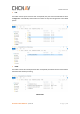
Software Overview ◼ LAS: This folder contains point cloud raw data. For Alpha3D, the point cloud raw data will be saved in Riegl folder automatically. Other folders are useless as they were designed for other LiDAR system. ◼ PARA: This folder contains four initial parameter files. For Alpha3D, this folder should contains below listed files after all data processing.
Software Overview After processing folder ◼ POST: This folder should contain both IE project file and POS file which generated after IE processing. The initial POST folder is empty. ◼ ROVER: This folder contains GNSS data and IMU data which recorded by Alpha3D. These two files will automatically save in this folder.
Software Overview ◼ SYNC: This folder contains log data and trig data of Alpha3D. ◼ TRACE: For Alpha3d, this folder is empty. 5.2.2.2 Base Data Processing GNSS data of base station is saved in receiver. Take CHC i80 as example, there are three download methods. First is USB mode download, copy static data form repo folder into computer; Second is Webpage mode download. Connect computer with receiver via Wi-Fi and input http://192.168.1.1 to log in.
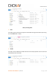
Software Overview ◼ Right click HCN file and click “Antenna Setting”. Input measured antenna height and select “Center of Bumper”, finally click “Phase Center” – “OK”. ◼ Right click HCN file and click “RINEX Option”. Change “RINEX version” as 3.02, change “Interval” as 0.2 and change “Splitting Interval” as 14400.
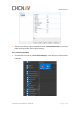
Software Overview ◼ After all above settings, right click HCN file and click “Convert Selected Files”. A new Rinex folder will be generated under original catalogue: 5.2.2.3 License Activation ◼ Click Windows and find the “Local License Manager” under Waypoint Inertial Explorer 8.80 folder.
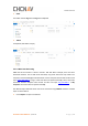
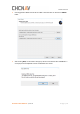
Software Overview ◼ Enter activation code here and click Activate to complete activation. ◼ If you want to log out, go to Local Licenses and click Return. 5.2.2.4 Data Format Conversion Double click IE icon to begin work. Before start POS processing, the data format of both base and rover need to be converted. Click “Tools - Convert Raw GNSS to GPB” to add all needed files and finally click “Convert”.
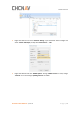
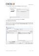
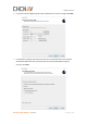
Software Overview Comparison before and after format conversion: Rover: Base: Notice: When convert rover files, double click IMU file and select SPAN Model as SPAN KVH1750. 5.2.2.5 POS Processing ◼ Click “File - New Project - Project Wizard” to create an IE project.
Software Overview ◼ Give it a directory location and project name. For convenience, it is recommend saving project in POST folder. Click Next.
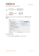
Software Overview ◼ Choose gpb file of GNSS and imr file from IMU. These two files can be found in ROVER folder. ◼ After clicking Next, an information will pop up which ask to add dmr file. Click NO as it’s an empty file unless Alpha3D connect to ODOmeter this sensor.
Software Overview ◼ For remote antenna height, keep all values as default and no need to change. Click Next. ◼ For base data, IE supports two options to load: First is from base station and second is download via PPP mode. Also, the precise file can also be downloaded to improve accuracy. Click Next.
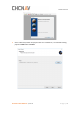
Software Overview ◼ IE supports maximum 32 base stations data for one project. Click “Add Station from File” and click Next to add base station data.
Software Overview ◼ For base station data, the coordinates, ellipsoidal height and datum information are needed. Enter the measured height value and choose relative measure type. Click Next.
Software Overview ◼ Finally, the project wizard will show details of this project. Click Finish to load trajectory.
Software Overview 5.2.2.6 GPS/INS Combine Processing The IE software supports two INS processing dialogues: Loosely Coupled & Tightly Coupled. Loosely Coupled is a two-step process which is not suitable if GPS signal is bad; Tightly Coupled is a one-step process which always be chose in mobile mapping solution. Here take tightly coupled dialogue as an example: ◼ Click Process - Process TC (Tightly Coupled) to start processing. Select Multi-pass to improve accuracy and enter lever arm values in below.
Software Overview ◼ When processing finished, the trajectory should be shown in interface: ALPHA3D USER MANUAL | 2019-06 P a g e | 77
Software Overview 5.2.2.7 Export POS File ◼ Click Output - Export Wizard to export POS result. ◼ Choose HUACE Pos profile which should be copied into export_templates folder under IE folder. For example: C:\NovAtel\InertialExplorer870\resources\export_templates.
Software Overview ◼ Select Use processing datum and click Next ◼ Select suitable grid which used for transformation.
Software Overview ◼ Select Time Interval as 0.005s, ensure below lever arm values are correct. Click Finish to export POS file which used for next step processing.
Software Overview 5.3 CoPre - Point Cloud Processing Software 5.3.1 CoPre Software Overview CoPre is a CHC designed one-button data pre-processing software enables both point cloud processing and panorama image collation. It also supports lots of powerful functions such as custom coordinate system, panorama stitching, point cloud colorized and depth image.
Software Overview ◼ The custom coordinate system interface should pop up. Ensure Ellipsoid and Projection information are correct, then click Confirm.
Software Overview ◼ In project wizard interface, keep all settings as default and click Next. Next page is a processing flow which supports automatically processing data. Here we choose manually processing data so click Finished. The interface will show project information on right side and relative files will be read automatically if they saved in correct folders before. 5.3.2.2 Solve Point Cloud Data ◼ Click Solve to automatically start raw lidar data (rxp format) processing.
Software Overview 5.3.2.3 Picture Collation Click Picture to prepare picture collation. Ensure sequence number is start from 1 and keep all settings as default. Click Start Collation. Detailed progress is shown in below information box. It will generate jpg format picture in PANO folder.
Software Overview ALPHA3D USER MANUAL | 2019-06 P a g e | 85
Software Overview 5.3.2.4 Point Cloud Colorized Click Colorize to start point cloud colorized. Both needed files will be automatically read in software and click Start to begin. It will generate colorized las format point cloud data in ColorLas folder.
Alpha3D Operation Quick Guide 6 Alpha3D Operation Quick Guide 6.1 Pre-Requirement for Installation In order to install and use Alpha3D, the following requirements must be covered: For safety, at least 2 persons to lift and mount the unit. A vehicle with roof bar to assemble system. A base station to post-processing data. 6.2 Operation Steps First, assemble extension with roof bar which above the vehicle and then mount Alpha3D system, detailed steps please check Part 3.6.1.
Alpha3D Operation Quick Guide 6.3 Data Pre-Processing Steps Pre-processing is the first stage in the data processing process which can generate trajectory, point cloud and panoramic pictures finally. During this process, there are two software will be used: Inertial Explorer and CoPre. Inertial Explorer is first used to combine both base and rover data to generate trajectory POS file. Detailed steps please check Part 5.2.2.
Safety Directions 7 Safety Directions 7.1 General Requirements LiDAR system is a complex and precise surveying system. During daily carry, transport, use and store process, only correct using and proper maintenance can ensure the accuracy of unit and extend the durable years of unit. There are follow requirements need to be noticed: ◼ ◼ ◼ ◼ ◼ ◼ ◼ ◼ ◼ ◼ ◼ Users are not allowed to disassemble unit by self. If unit occurred problems, please contact CHC support team first.
Safety Directions ◼ carton and filling with shock absorbing cotton or foam inside. Buy a special insurance and labeled as dangerous package. Alpha3D should be used and storage by special person and don’t rent device to other people. 7.3 Alpha3D Using Tips ◼ ◼ ◼ ◼ ◼ ◼ ◼ ◼ During usage process, Alpha3D must be handled with care in order to avoid dirty and scratch. Don’t sit on instrument container or packing box.
Safety Directions FCC WARNING STATEMENT This equipment has been tested and found to comply with the limits for a Class B digital device, pursuant to part 15 of the FCC Rules. These limits are designed to provide reasonable protection against harmful interference in a residential installation. This equipment generates, uses and can radiate radio frequency energy and, if not installed and used in accordance with the instructions, may cause harmful interference to radio communications.