CHC® P5™ GNSS Reference Receiver User Guide Revision 1.
Table of Contents Table of Contents Table of Contents .................................................................................................. 2 Safety Information ................................................................................................ 4 Regulations and Safety .......................................................................................... 4 Type Approval ........................................................................................................
Table of Contents 5 Configuring the Receiver: Keypad, Indicator LEDs, and Display ...........................25 5.1 Button Functions ............................................................................................ 25 5.2 Indicator LEDs ................................................................................................ 26 5.3 Home Screen .................................................................................................. 26 5.4 Status Screens ..........................
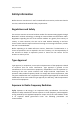
Safety Information Safety Information Before the user uses the user’s CHC® P5 GNSS reference receiver, make sure that the user has read and understood all safety requirements. Regulations and Safety The receiver contains an internal wireless modem for communicating signals through Bluetooth® wireless technology or through an external data communications radio. Regulations regarding the use of the wireless modem vary greatly from country to country.
Safety Information (1) Do not operate the transmitter when someone is 20 cm (7.8 inches) of the antenna. (2) Do not operate the transmitter unless all RF connectors are secured, and any open connectors are correctly terminated. (3) Do not operate the equipment near electrical blasting caps or in an explosive atmosphere. (4) All equipment must be correctly grounded for safe operation. (5) All equipment should be serviced only by a qualified technician.
Safety Information WARNING – Charge and use the rechargeable Lithium-ion battery only in strict accordance with the instructions. Charging or using the battery in unauthorized equipment can cause an explosion or fire and can result in personal injury and/or equipment damage. To prevent injury or damage: (1) Do not charge or use the battery if it appears to be damaged or leaking. (2) Charge the Lithium-ion battery only in a CHC product that is specified to charge it.
1 Introduction The P5 GNSS Reference Receiver User Guide describes how to set up and use the CHC® P5 GNSS reference receiver. In this manual, “the receiver” refers to the P5 GNSS reference receiver unless otherwise stated. Even if the user has used other Global Navigation Satellite Systems (GNSS) products before, CHC recommends that the user spend some time reading this manual to learn about the special features of this product. If the user is not familiar with GNSS, go to www.chcnav.
1.3 Disclaimer Before using the receiver, please make sure that the user has read and understood this User Guide, as well as the safety requirements. CHC holds no responsibility for the wrong operation by users and for the losses incurred by the wrong understanding about this User Guide. However, CHC reserves the rights to update and optimize the contents of this guide regularly. Please contact the user’s local CHC dealer for new information. 1.
2 Overview This chapter introduces the P5 GNSS reference receiver (“the receiver”). This receiver makes it easy to set up a powerful and reliable Continuously Operating Reference Station (CORS) or to collect data from temporary field locations. The receiver is ideal for the following infrastructure applications: (1) As part of a GNSS Infrastructure network in conjunction with CHC Reference Station Network (CPS) software. (2) As part of a permanent reference station with or without supporting software.
2.1.1 The Network Appliance Concept Traditionally, a GNSS receiver has one operator. That person is the only user of the receiver, so they can change settings without affecting other users. With the P5 GNSS reference receiver, an operator can configure a receiver once, and then make it available as a network appliance for general use by one or more users (or clients).
2.
2.4 Use and Care This receiver can withstand the rough treatment and tough environment that typically occurs in CORS installation. However, it is a high-precision electronic instrument and should be treated with reasonable care. CAUTION – Operating or storing the receiver outside the specified temperature range can damage it. For more information, see Chapter 8 Specifications. 2.5 Electronic Interface High-power signals from a nearby radio or radar transmitter can overwhelm the receiver circuits.
2.6 Keypad and Display 1 2 3 5 4 Feature Description Feature Indicator LEDs Buttons Shows the working status. See 5.2. Indicator LEDs Indicator LEDs Buttons Display Mini USB port 4G card slot Use to turn on, turn off or configure the receiver. See 5.1. Button functions. This LCD enables the user to view the current configuration settings of the receiver and the operation by operators. See 5.3. Home screen. Support DEVICE/HOST.
2.7 Rear Connectors 1 4 2 5 3 6 7 No. Connector type Description 1 2 3 4 5 TNC DB9 TNC TNC RJ45 jack 6 LEMO (10-pin) Port 2 7 TNC Connect to the GNSS antenna. RS-232 serial port, 9-pin male connector. Connect the 4G antenna to enhance the 4G signal. Connect to the atomic clock for time calibration.
3 Batteries and Power The P5 GNSS reference receiver uses an internal rechargeable Lithium-ion battery, which can be replaced only at an Authorized CHC Service Center. The receiver can also be powered by an external power source that is connected to the LEMO ports. The operational time provided by the internal battery depends on the type of measurement and operating conditions. Typically, the internal battery provides up to 24 hours operation.
WARNING – When the user applies DC voltage to this product through the LEMO connector, the DC voltage must be limited to 36V DC +0% under both normal and single fault conditions. This product may present an electrical hazard if the recommended input voltage is exceeded. 3.2 Battery Safety The receiver is powered by a rechargeable internal Lithium-ion battery. Charge and use the battery only in strict accordance with the following instructions. WARNING – Do not damage the rechargeable Lithium-ion battery.
(2) Do not use at extreme temperatures. The receiver is designed to operate at -40 °C to +65 °C (-40 °F to +149 °F). However, operation at temperatures of less than 0 °C (32 °F) can cause a rapid drop in battery life. 3.4 Charging the Battery The rechargeable Lithium-ion battery is supplied partially charged. Charge the battery completely before using it for the first time. If the battery has been stored for longer than three months, charge it before use.
3.6 Removing the Battery The internal Lithium-ion battery may be removed only at an authorized CHC Service Center. If the battery is removed at an unauthorized service center, the remaining warranty on the product will be void.
4 Setting Up the Receiver This chapter describes best practices for setting up the equipment and outlines the precautions that the user must take to protect the equipment. It also describes the typical installation diagram of reference station composed of P5 GNSS receiver, GNSS antenna, external power and network cable. The antenna installation guidelines described here are the minimum standards.
4.1.3 Uninterruptible Power Supply CHC recommends that the user use an uninterruptible power supply (UPS) to power the receiver. The internal battery can also operate as a UPS for up to 24 hours. A UPS protects the equipment from power surges and spikes and keeps the receiver running during short power outages. For more information, contact the user’s local CHC dealer. 4.1.4 Lighting and Surge Protection CHC recommends that the user install lightning protection equipment at permanent sites.
transmitting station, high voltage wires) at least 200 m (656 feet) Mounted 1.5 m (5 feet) above any nearby signal reflectors. Mount stability that is not influenced by thermal expansion, wind loading, or soil expansion/contraction. For additional information on this topic, research the reference antenna installation guidelines published by the: US National Geodetic Survey (http://www.ngs.noaa.gov/PUBS_LIB/CORS_guidelines.pdf) International GNSS Service (http://igscb.jpl.nasa.
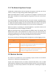
4.2.2 System Installation Diagram The typical installation diagram of the CHC P5 GNSS receiver connected with CHC A220GR GNSS Geodetic Antenna, external power supply, and network cable.
CHC AT312 GNSS Network Cable Geodetic Antenna GNSS Antenna Cable CHC Data Cable Adapter (1) Install the GNSS antenna at the appropriate location (see 4.1.5. Placing the antenna for the guidelines); connect the antenna to the TNC Plug Socket of P5 via the GNSS Antenna Cable. (2) Power the P5 by an external power source (e.g., mains supply) with Adapter via CHC Data Cable. a) Connect the 10-pin LEMO of CHC Data Cable of P5.
c) Connect two leg plugs or three leg plugs of Adapter to the mains supply. (3) Connect the network cable to the RJ45 jack of P5 to link the P5 with the network. Notes: Also, the P5 can be powered by external battery via CHC Data Cable. And the power supply voltage should be controlled between 12 to 36 V DC.
5 Configuring the Receiver: Keypad, Indicator LEDs, and Display The P5 GNSS reference receiver features a front panel user interface with a keypad, four indicator LEDs, and a two-line alphanumeric display. This interface enables the user to configure many of the receiver’s features without using an external controller or computer. 5.1 Button Functions Use the buttons on the front panel to turn on or turn off the receiver and to check or change the receiver settings.
5.2 Indicator LEDs Indicator LEDs Name Color Power LED Green/ Red Satellites LED Correction LED Network LED Descriptions The indicator to show whether GNSS is on or off. Green: The receiver operates in the absence of a power supply. Yellow-green: the status of charging and normally operating. Red: Not booting and the status of charging. Green Shows the number of satellites that the receiver has tracked. When the receiver is searching satellites, the green LED flashes once every 5 seconds.
The name of the product. The position solution. The number of satellites being tracked. As a power-saving feature, the front panel goes dark after a short period of inactivity. If the display is not lit and the receiver is on, press ANY BUTTON to reactivate the display. 5.4 Status Screens To review the receiver's current settings in the status screens, press on the front panel.
Battery Temperature Internal Temperature Environment Temperature Internal storage memory remaining Receiver hardware version and software version Firmware Version Receiver serial number and part number Resume 5.5 Setting Up the Receiver as Part of An Ethernet Configuration Use the keypad to set up the receiver as part of an Ethernet configuration. Press or to move between different status screens, and then press enter the edit mode.
6 Configuring the Receiver: Other Than Keypad and Display The user can configure the P5 GNSS reference receiver to perform a wide variety of functions. This chapter describes the configuration methods other than the front panel display and explains when and why each method is used. 6.1 Configuring the Ethernet Settings The receiver Ethernet port connects to an Ethernet network, through which the user can access, configure, and monitor the receiver. No serial cable connection to the receiver is necessary.
6.
6.2.1 Changing the Settings The web interface shows the configuration menus on the left of the browser window, and the setting on the right. Each configuration menu contains the related submenus to configure the receiver and monitor receiver performance. This section describes each configuration menu. To view the web interface in another language, select the corresponding language name from the drop-down list in the upper right corner of the interface. Currently, three languages are available: 6.2.1.
(1) Position This page shows the relevant position information about the receiver's position solution which including the position, DOP values, satellites used and tracked, and the receiver clock information. (2) Activity Lists several important items to help the user understand how the receiver is being used and its current operating condition. Items include the identities of currently tracked satellites, internal and external storage usage rate.
6.2.1.2 Satellites Menu Use the Satellites menu to view satellite tracking details and enable/disable GPS, SBAS, GLONASS, BDS and Galileo constellations. These menus include tabular and graphical displays to provide all required information on satellite tracking status.
(2) Tracking Graph The following figure is an example of satellite track diagram page. Users can determine the satellite types and the corresponding SNR to be displayed in any combination. (3) Tracking SkyPlot The following figure is an example of Skyplot page.
(4) Tracking Activation In this submenu, users can enable/disable GPS, SBAS, GLONASS, BDS and Galileo constellations. (5) Tracking enable In this submenu, users can enable/disable the signals of each constellation. Please click [Confirm] button after the users finish the collection.
6.2.1.3 Receiver Configuration Menu Use this menu to configure settings such as the antenna type and height, elevation mask and PDOP setting, the reference station coordinates, receiver resetting and web interface language: (1) Summary This submenu shows the receiver information and reference station information, including antenna related information, elevation mask angle, reference station work-mode and position, etc.
(2) Antenna configuration Use this screen to configure all the items relating to the GNSS antenna. The user must enter the correct values for all antenna-related fields, as the choices the user makes significantly affect the accuracy of logged data and broadcast RTK correctors: (3) Reference Station Settings Use this screen to configure settings such as the station coordinates.
For Reference Station Mode: There are three available options: Auto Rover, Auto Base, and Manual Base. Auto Rover: The receiver will serve as Rover after the user restarts the receiver each time. Auto Base: The receiver will serve as Base after the restart, and then broadcast RTK correctors based on coordinates obtained through single-point positioning automatically.
Manual Base: The receiver will serve as Base after the restart, and then broadcast RTK correctors based on the coordinates before power off. For Reference Latitude and Reference Longitude: There are mainly three methods to enter the reference coordinates and shown as follows: Acquire Current Position: Click this button to acquire current position obtained through single-point positioning automatically. Manual Input: Manually input the known coordinates.
(5) Languages Use this screen to select the web interface language: (6) User management Use this screen to edit user management: (7) USB function Switch Use this screen to switch USB function: (8) HCPPP Settings Use this screen to set HCPPP: 40
(9) else settings Use this screen to set :1PPS, clockswitch, psrsmooth, simuator. 6.2.1.4 Data Recording Menu Use the Data Logging menu to set up the receiver to log static GNSS data and to view the logging settings. The user can configure settings such as observable rate, recording rate, continuous logging limit, and whether to auto delete old files if memory is low.
(1) Log Settings This page shows the data logging status, internal and external storage usage and data logging status of each storage thread. Also, users can configure the data logging settings for each storage thread, including recording name, saving location, storage limit, store formats, start time, etc. To open or close all the storage threads, click the [ON] or [OFF] button at the Switch field. Notes: The [ON] and [OFF] button to the right of Log Status field are the Master Log Switch.
In this screen, the user can set all data logging parameters, and determine whether the recording files will be affected by the FTP Push. The main parameters are as follows: a) Auto Record: Select “Yes” or “No” to determine whether to log data when the Master Log Switch is ON. b) Sample Interval: Select the observable rate from the dropdown list. c) Store Location: Determine whether to store in internal storage or external storage. d) Start Date: Set the start time of data log in UTC.
to the right of the required FTP server, and the FTP Push Settings screen appears: (3) FTP Push Recording Shows the related information about the recorded filed that be pushed. And users can click [Clear FTP Push Log] in the upper right corner to clear the status of FTP Push operations. (4) Data Download In this submenu, users can download the data files that recorded in the internal storage through the internal FTP site. Also, the user can directly download the static data through file explorer.
The default login account for the internal FTP site is: Username: ftp Password: ftp Click the directory named logs/ to view and download the files currently stored on the receiver: To find the file need to be downloaded, click the name of storage folder (“logs_” plus with the number of the storage thread) the date of the file that be recorded the format of the file the name of the target file.
To download a file, left-click the name of the target file download the file according to the prompts. b) Use File Explorer According to the IP of the P5 receiver, in the writer’s case, Input ftp://192.168.32.161/ into the File Explorer. Press Enter and the user can download the data from the logs folder after successful login the internal FTP site (same account as given above): The path of the static data is inside the “logs” folder, the same with the downloading path from the website.
(5) Distance Download Use this function to login data after you set port forwarding. 6.2.1.5 I/O Settings Menu Use the I/O Settings menu to set up all receiver outputs and inputs. The receiver can output CMR, RTCM, Raw data, Ephemeris data, GPGGA, GPGSV, on TCP/IP, UDP, serial port, or Bluetooth ports. The following figure shows an example of the screen that appears when the user selects this submenu.
In this submenu, users can configure 4 types of input and output settings. (1) RTK Client After configuring the settings of RTK client, users can log on CORS or APIS. Click the [Connect] button to the right the I/O Settings screen will appear choose one of the connection protocols among the NTRIP, APIS_BASE, and APIS_ROVER configure the related parameters click [Confirm] to log on CORS or APIS.
c) Connection Protocol: APIS_ROVER d) TCP/UDP Client Click the [Connect] button to the right of required TCP/UDP Client the TCP/UDP Client screen will appear select the connection protocol from the dropdown list enter the IP and Port of the target server configure messages that the user want to output to the target server click [Confirm] to save and complete the connection.
Notes: If the receiver and server are under the same Local Area Network (LAN), users can use the IP address in LAN of the server with any Port. However, if the receiver and server are under the two different LAN, users should use the public IP address of the server and configure the port mapping of the server.
b) Connection Protocol: TCP (3) COM Port Click the [Settings] button on the right of required COM Port row the Serial Port Setup screen will appear select Baud Rate used to transmit data configure the messages that the user want to output through the serial port click [Confirm] to save the settings and start to transmit.
Notes: For the “Serial Port (DB9)”, it is compatible with connection with external meteorograph. (4) Bluetooth Click the [Settings] button on the right of Bluetooth row the Bluetooth Set screen will appear configure the messages that the user want to transmit through Bluetooth click [Confirm] to save the settings and start to transmit.
6.2.1.
(2) Wired Network Setting Use this submenu to configure the related parameters of the Network, including static IP, subnet mask, etc. (3) Mobile Network Setting Use this submenu to configure the settings of the Network, then support mobile network.
(5) HTTP (6) HTTPS (7) FTP Service 6.2.1.7 Network Security Menu Use this menu to check and configure the Network Security.
(1) Firewall (2) Port filtering Use this submenu to control the access to the corresponding port of the receiver. (3) MAC filtering Use this submenu to control the computer’s access to the receiver on the LAN.
(4) Service ports 6.2.1.8 Module Setting Menu Use this menu to check and configure the Module settings.
(2) Wi-Fi Settings Use this submenu to configure the related parameters of the Wi-Fi settings, including Wi-Fi mode, encrypt type, password, etc.
6.2.1.9 Firmware Menu Use this menu to check the current firmware information, download the system log, update the receiver firmware, download or update the configuration file and register the receiver. (1) Firmware Info Use this submenu to check the current firmware information. The following figure shows an example of the firmware information. (2) The Hardware Version Use this submenu to check the current hardware information. The following figure shows an example of the hardware information.
In this submenu, users can download the configuration file by clicking [Download] button and determine a saving path to download the configuration file (.cfg file). Also, users can click the [Browse] button to locate the existing configuration file click [Confirm] button to confirm the selected file and start updating. (4) System Log Use this submenu to download the system log of the receiver. (5) User Log Use this submenu to tick which logs files and downloads the user log of the receiver.
Use this submenu to load new firmware to the receiver across the network. Click the [Browse] button to locate the upgrade file click [Confirm] button to confirm the selected upgrading file and start upgrading. Notes: It will take about 2 or 3 minutes to complete the firmware upgrading. (7) Board Upgrade Use this submenu to upgrade board. Click [Browse] to choose upgrade files and Click [Confirm] to upgrade. (8) Upgrade Online (9) GNSS Registration Use this submenu to register the receiver.
7 Default Setting and Configuration Files Most of the receiver settings are stored in application files. The default application file, Default.cfg, is stored permanently in the receiver and contains the factory default settings for the P5 GNSS reference receiver. Whenever the receiver is reset to its factory defaults, the current settings (stored in the current configuration file, copy.cfg) are reset to the values in the default application file.
7.1.2 Resetting the Receiver to Factory Defaults Log in the web page of the receiver tap and unfold the Receiver Reset menu tap the Receiver Reset submenu click the [Confirm] button to the right of Reset to Defaults field. 7.1.3 Using Configuration Files to Duplicate Receiver Settings The P5 GNSS reference receiver allows the extensive use of application files to retain a unique receiver configuration.
8 Specifications This chapter describes the specifications for the P5 GNSS reference receiver. Specifications are subject to change without notice. 8.
8.2 Communication Feature Specification RJ45 Jack DB9 male Ethernet 3-wire RS232, see C.III. CHC P5 receiver db9 male connector definition for details 9-wire RS232, see C.I.
8.3 Physical Feature Specification Size (L x W x H) Weight Operating temperature Storage temperature Humidity Water and Dustproof 200 x 150 x 69 mm (7.9 x 5.9 x 2.7 in) 2.15 kg (75.8 oz) -40 °C to +65 °C (-40 °F to +149 °F) -45 °C to +80 °C (-49°F to 176°F) 100% condensation Tested to IP67; waterproof for temporary immersion to a depth of 1 m (3.28 ft) for 30 minutes; dustproof Designed to survive a 1 m (3.28 ft) drop onto concrete Shock and Vibration 8.
8.5 General Feature Specification Front panel display Power button and indicator LED Escape, OK and 4 arrow keys (up, down, left, right) USB port and 4G slot LCD GNSS reference receiver CHC AT312 GNSS Geodetic antenna or CHC C220GR2 GNSS Choke Ring antenna preferred. Other models supported. Receiver type Antenna type 8.
Upgrading the Receiver Firmware A. Upgrading the Receiver Firmware The receiver is supplied with the latest version of the receiver firmware already installed. If a later version of the firmware becomes available, use the USB device to upgrade the firmware on the user’s receiver. For the latest firmware resource, please consult the user’s local CHC dealer. The user can also upgrade the receiver through the web interface.
B. Troubleshooting Use this appendix to identify and solve common problems that may occur during the use of the receiver. Please read this section before contact CHC Technical Support. B.I. Receiver Issues This section describes some possible receiver issues, possible causes, and how to solve them. Issue Possible cause Solution The receiver does not turn on. External power is too low. Check the charge on the external battery and, if applicable, check the fuse. Check the charge on the internal battery.
satellites. The receiver is not responding. The receiver is not receiving satellite signals than four satellites are tracked. The receiver needs a soft Turn off the receiver and reset. then turn it back on again. The GNSS antenna cable Make sure that the GNSS is loose. antenna cable is tightly seated in the antenna connector on the GNSS antenna. The cable is damaged. Check the cable for any signs of damage. A damaged cable can inhibit signal detection from the antenna at the receiver.
C. Communication Ports Definition C.I.
C.II.
D. Glossary Terms Description Base Station Also called reference station. A base station in construction is a receiver placed at a known point on a job site that tracks the same satellites as an RTK rover and provides a real-time differential correction message stream through the radio to the rover, to obtain centimeter level positions on a continuous real-time basis.
simultaneously at a base station. Because the base station is in a known location, any errors in data collected at the base station can be measured, and the necessary corrections applied to the rover data. Differential correction can be done in real-time, or after the data has been collected by postprocessing. Differential GPS See real-time differential GPS. DOP Dilution of Precision. A measure of the quality of GPS positions, based on the geometry of the satellites used to compute the positions.
satellites. Normally set to 10 degrees to avoid interference problems caused by buildings and trees, and multipath errors. Ephemeris/Ephemerides A list of predicted (accurate) positions or locations of satellites as a function of time. It contents a set of numerical parameters that can be used to determine a satellite’s position. Available as broadcast ephemeris or as postprocessed precise ephemeris. Epoch The measurement interval of a GPS receiver.
user’s position yield would be decreased by the vertical component of the PDOP ( for example, if the user is collecting data under canopy). L1 The primary L-band carrier used by GPS satellites to transmit satellite data. L2 The secondary L-band carrier used by GPS satellites to transmit satellite data. L5 The third L-band carrier used by GPS satellites to transmit satellite data. L5 will provide a higher power level than the other carriers.
PDOP Position Dilution of Precision. PDOP is a DOP value that indicates the accuracy of three-dimensional measurements. Other DOP values include VDOP (vertical DOP) and HDOP (Horizontal Dilution of Precision). Using a maximum PDOP value is ideal for situations where both vertical and horizontal precision is important. Postprocessing Postprocessing is the processing of satellite data after it has been collected, in order to eliminate the error.
commission established to define a differential data link for the real-time differential correction of roving GPS receivers. There are three versions of RTCM correction messages. All CHC GPS receivers use Version 2 protocol for single-frequency DGPS type corrections. Carrier phase corrections are available on Version 2, or on the newer Version 3 RTCM protocol, which is available on certain CHC dual-frequency receivers. The Version 3 RTCM protocol is more compact but is not as widely supported as Version 2.
provide corrections to each rover that are more accurate than corrections from a single base station. To use the VRS corrections, the rover sends its position to the VRS server. The VRS server uses the reference station data to model systematic errors (such as ionospheric delay) at the rover position. It then sends RTCM or CMR correction messages back to the rover. WAAS Wide Area Augmentation System.
CHC - Shanghai Huace Navigation Technology Ltd. 599 Gaojing Road, Building D Shanghai, 202103, China Tel: +86 21 542 60 273 Fax: +86 21 649 50 963 Email: | support@chcnav.com Website: www.chcnav.