CHC® i50 GNSS Receiver User Guide Revision 1.
Table of Content Table of Content Table of Content.................................................................................................... 2 Preface ................................................................................................................. 5 Copyright ................................................................................................................ 5 Safety Warnings .............................................................................................
Table of Content 5 4.1 Rover Station Setup Guidelines................................................................ 29 4.2 Rover Station Setup.................................................................................. 30 Configuring Through a Web Browser ..............................................................31 5.1 Status Menu ............................................................................................. 32 5.1.1 Position Submenu .............................................
5.8.1 Firmware Info Submenu................................................................... 63 5.8.2 Hardware Version Submenu ............................................................ 63 5.8.3 Config File Submenu ........................................................................ 63 5.8.4 System Log Download Submenu...................................................... 64 5.8.5 User Log Submenu ........................................................................... 64 5.8.
Preface Preface Copyright Copyright 2016-2017 CHC | Shanghai Huace Navigation Technology Ltd. All rights reserved. The CHC are trademark of Shanghai Huace Navigation Technology Limited. All other trademarks are the property of their respective owners. Trademarks All product and brand names mentioned in this publication are trademarks of their respective holders. Safety Warnings The Global Positioning System (GPS) is operated by the U.S.
Preface CE Interference Statement Declaration of Conformity: Hereby, Shanghai Huace Navigation Technology Ltd. declares that this i50 is in compliance with the essential requirements and other relevant provisions of Directive 2014/53/EU. A copy of the Declaration of conformity can be found at Shanghai Huace Navigation Technology Ltd.
Introduction 1 Introduction The i50 GNSS Receiver User Guide describes how to set up and use the CHC® i50 GNSS receiver. In this manual, “the receiver” refers to the i50 GNSS receiver unless otherwise stated. Even if you have used other Global Navigation Satellite Systems (GNSS) products before, CHC recommends that you spend some time reading this manual to learn about the special features of this product. If you are not familiar with GNSS, go to www.chcnav.com for an interactive look at CHC and GNSS. 1.
Introduction 1.1.3 Use and Care This receiver is designed to withstand the rough environment that typically occurs in the field. However, the receiver is high-precision electronic equipment and should be treated with reasonable care. CAUTION - Operating or storing the receiver outside the specified temperature range will cause irreversible damage. 1.2 Technical Support If you have a problem and cannot find the information you need in this manual or CHC website (www.chcnav.
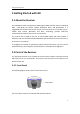
Getting Started with i50 2 Getting Started with i50 2.1 About the Receiver The i50 GNSS receiver incorporates a GNSS engine, GNSS antenna, internal radio (410 MHz – 470 MHz), 4G cellular modem, Bluetooth, Wi-Fi, and dual-battery in a ruggedized and miniature unit that is easy for you to set up an all-in-one RTK rover or mobile base station. Bluetooth and Wi-Fi technology provide cable-free communication between the receiver and controller.
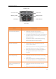
Getting Started with i50 Satellite LED Correction LED Static LED Battery A LED Battery B LED Fn button Power button Wi-Fi LED Name Description Correction LED (Green) • Indicates whether the receiver is transmitting/receiving differential data. • The green LED flashes once per second when As a Base station: successfully transmitting differential data. As a Rover station: successfully receiving differential data from Base station.
Getting Started with i50 LED flashes. Wi-Fi LED (Red) • Indicates whether the receiver Wi-Fi is opened. • When the receiver Wi-Fi is opened, the red LED turns on. Fn button • Move to next line of the menus or options. • Move to next character of the value that you want to make change. • Cancel the change you make on a function. Power button • Works as a Power button: • Press and hold this button for 3 seconds to turn on or turn off the receiver.
Getting Started with i50 2.2.3 Receiver Ports Port Name Description IO port • This port is a 7-pin Lemo connector that supports RS-232 communications and external power input. • Users can use GPS to PC Data Cable supplied with the system to realize RS-232 communications between the receiver and computer or controller. Also, users can use a 7-pin cable to transmit differential data to an external radio. USB port • This port is a mini-USB connector that supports USB communications.
Getting Started with i50 2.3 Batteries and Power 2.3.1 Internal Batteries The receiver has two rechargeable Lithium-ion batteries, which can be removed for charging. 2.3.1.1 Charging the Battery The rechargeable Lithium-ion battery is supplied partially charged. Charge the battery completely before using it for the first time. To charge the battery, first remove the battery from the receiver, and then place it in the battery charger, which is connected to AC power.
Getting Started with i50 •Do not expose the battery to fire, high temperature, or direct sunlight. •Do not immerse the battery in water. •Do not use or store the battery inside a vehicle under hot weather condition. •Do not drop or puncture the battery. •Do not open the battery or short-circuit its contacts. WARNING - Avoid contact with the rechargeable Lithium-ion battery if it appears to be leaking. Battery fluid is corrosive, and contact with it can result in personal injury and/or property damage.
Getting Started with i50 In the field: The external power cable is connecting with a vehicle battery, the output port of the external power cable connects with the Power Port of the GPS to PC Data Cable. WARNING - Use caution when connecting external power cable's clip leads to a vehicle battery. Do not allow any metal object to connect (short) the battery's positive (+) terminal to either the negative (-) terminal or the metal part of the vehicle battery.
Getting Started with i50 Push down Battery cover Battery bail Insert the SIM card with the contacts facing upward, as indicated by the SIM card icon next to the SIM card slot. To eject the SIM card, slightly push it in to trigger the spring-loaded release mechanism. Tip – The SIM card is provided by your cellular network service provider. 2.5 Product Basic Supply Accessories 2.5.
Getting Started with i50 USB Cable GPS to PC Data Cable Lithium Battery H.I. Tape Extension pole Tribrach with optical plummet Auxiliary H.I.
Getting Started with i50 2.5.2 Rover Kit Basic Supply Item Picture i50 GNSS Receiver UHF Bar Antenna (410-470 MHz) USB Cable GPS to PC Data Cable Battery Charger Power Adapter with Cord Lithium Battery 2M Range Pole w/bag Auxiliary H.I.
Getting Started with i50 Transport Hard Case 2.6 Connecting to an Office Computer The receiver can be connected to an office computer for serial data transfer or settings via a GPS to PC Data Cable. Before you connect to the office computer, ensure that the receiver is powered on by internal battery or external power. The following figure shows how to connect to the computer for serial data transfer or settings: GPS to PC Data Cable 2.7 Connecting to a Controller 2.7.
Getting Started with i50 Tap the Wireless Lan icon on the right side to select the hot-spot → Switch on the WiFi module by the top switch → tap refresh button to search the hot spot around → select the target device in the list. Tap Connect to link to the hot spot. If the first-time connection to this hot spot, user may type in the password.
Getting Started with i50 Tip – The Wi-Fi key of the receiver is 12345678 by default. Tap the Connect button to build the connection. 2.7.2 Connecting via Bluetooth with LandStar 7 Software Turn on the controller → run LandStar 7 → go to Config main menu → tap Connect. In the Connect screen, select CHC for the Manufacture field, i50 for Device Type field, Bluetooth for Connection Type field.
Getting Started with i50 Tap the Bluetooth Manager and turn on the Bluetooth function to search bluetooth device around → select the target device in the list.
Getting Started with i50 Tap the Connect button to build the connection. 2.8 Downloading Logged Data Data logging involves the collection of GNSS measurement data over a period at a static point or points, and subsequent post-processing of the information to accurately compute baseline information. Data logging using receivers requires access to suitable GNSS post-processing software such as the CHC Geomatics Office (CGO) Software.
Getting Started with i50 Switch on the receiver and connect it with a computer by USB Cable. After the successful connection, a removable disk named as the Serial Number (SN) of the receiver will appear on the computer. Double click the removable disk and you will see the folder named as “repo”. Double click this folder, you will see 9 folders. The “push_log” folder is used to save the log files, and the other 8 folders represent different logging session and are used for store static data.
Base Station Setup and Operation 3 Base Station Setup and Operation Real-Time Kinematic (RTK) operation provides centimeter-level precision by eliminating errors that are present in the GNSS system. For all RTK operations, you require both a rover receiver and a source of corrections from a base station or network of base stations. A base station consists of a receiver that is placed at a known point. The receiver tracks the same satellites that are being tracked by the rover receiver simultaneously.
Base Station Setup and Operation • • • communications tower. Do not set up the base station close to the sources of electromagnetic interference, include alternators and generators, electric motors, equipment with DC-to-AC converters, etc. Do not operate the receiver outside the specified operating temperature range 40°C to +60°C (-40°F to +140°F). Take reasonable care to keep the GNSS receiver equipment dry, which could prolong their life and reduce the effects of corrosion on ports and connectors. 3.
Base Station Setup and Operation Slant height 3.3 Outputting Corrections Using External Radio For base receiver part: 1. 2. 3. 4. 5. 6. Screw the i50 receiver onto extension pole. Screw the extension pole with auxiliary H.I. tool onto tribrach adaptor. Mount the tribrach onto the tripod. Insert the tribrach adaptor into the tribrach. Level and plumb the receiver over the known (control) point.
Base Station Setup and Operation 13. Set up the Datalink Antenna nearby the base receiver. 14. Fix the DL6 Datalink onto the tripod. 15. Place the car battery at an appropriate location. For connection between the receiver part and external radio part: 16. Connect Datalink Antenna to the Datalink Antenna Slot of DL6 Datalink via 3 meter Cable for Datalink Antenna. 17. Connect the base receiver with DL6 Datalink via GPS to Datalink Cable. 18.
Rover Station Setup And Operation 4 Rover Station Setup And Operation Real-Time Kinematic (RTK) operation provides centimeter-level precision by eliminating errors that are present in the GNSS system. For all RTK operations, you require both a rover receiver and a source of corrections from a base station or network of base stations. The second part of the RTK GNSS system is the rover receiver. The rover receiver is moved between the points that require measurement or stakeout.
Rover Station Setup And Operation • • track at least six satellites. To continue to survey at centimeter precisions, the rover must continuously track at least four satellites that the base station is also tracking. The radio link between the base and rover receivers must also be maintained. Loss of the satellite signals will result in a loss of centimeter position precision. 4.2 Rover Station Setup 1. 2. 3. 4. 5. If required, connect the radio antenna onto i50 receiver.
Configuring Through a Web Browser 5 Configuring Through a Web Browser Supported browsers: • • Google Chrome Microsoft Internet Explorer○R version 10, or higher To connect to the receiver through a web browser: 1. Turn on the Wi-Fi of the receiver. 2. Search the wireless network named as GNSS-XXXXXXX (the SN of your receiver) on your computer, and then establish the connection. 3.
Configuring Through a Web Browser This web page shows the configuration menus on the left of the browser window, and the setting on the right. Each configuration menu contains the related submenus to configure the receiver and monitor receiver performance. This chapter describes each configuration menu. To view the web page in another language, select the corresponding language name from the dropdown list on the upper right corner of the web page. Currently, three languages are available: 5.
Configuring Through a Web Browser 5.1.1 Position Submenu This page shows the relevant position information about the receiver's position solution which including the position, DOP values, satellites used and tracked, and the receiver clock information. 5.1.2 Activity Submenu Lists several important items to help you understand how the receiver is being used and its current operating condition.
Configuring Through a Web Browser 5.1.3 Google Map Submenu Tap this submenu to show the location of the receiver on Google map.
Configuring Through a Web Browser 5.2 Satellites Menu Use the Satellites menu to view satellite tracking details and enable/disable GPS, SBAS, GLONASS, BDS and Galileo constellations. These menus include tabular and graphical displays to provide all required information on satellite tracking status. 5.2.
Configuring Through a Web Browser 5.2.2 Tracking Info. Table Submenu The following figure is an example of satellite track diagram page. Users can determine the satellite types and the corresponding SNR of L-band carriers to be displayed in any combination. 5.2.3 Tracking Skyplot Submenu The following figure is an example of Skyplot page. 5.2.4 Satellite Activation Submenu Use this menu to enable or disable satellites.
Configuring Through a Web Browser 5.2.5 Tracking Enable Submenu Use this menu to enable or disable tracking signals.
Configuring Through a Web Browser 5.3 Receiver Configuration Menu Use this menu to configure settings such as the antenna type and height, elevation mask and PDOP setting, the reference station coordinates, receiver resetting and web interface language: 5.3.1 Description This submenu shows the receiver information and reference station information, including antenna related information, elevation mask angle, reference station work mode and position, etc. 5.3.
Configuring Through a Web Browser 5.3.3 Reference Station Settings Submenu Use this screen to configure settings such as the station coordinates and the broadcast station identifiers.
Configuring Through a Web Browser b) Auto Base: The receiver will serve as a base after this mode is enabled, and then broadcast correction data based on coordinate inputted by user, or obtained through autonomous positioning automatically. c) Manual Base: The receiver will serve neither as a base or a rover after this mode is enabled. Users need to configure the receiver manually.
Configuring Through a Web Browser For Reference Latitude and Reference Longitude: There are mainly three methods to enter the reference coordinates and shown as follows: a) Acquire Current Position: Click this button to acquire current position obtained through autonomous positioning automatically. b) Manual Input: Manually input the coordinate of a control point. c) From CORS: After the receiver logging in CORS, the software can record the coordinate of current position based on fix solution.
Configuring Through a Web Browser will be served as the coordinate of current positon. If users need to save the changes, please tap button. 5.3.4 Receiver Reset Submenu Use this screen to completely or partially reset the receiver: 5.3.5 Languages Submenu Use this screen to select the web interface language: 5.3.
Configuring Through a Web Browser 5.3.7 USB Function Switch Submenu Use this menu to switch between USB personal area network and Multimedia storage. 5.3.8 HCPPP Settings Submenu Use this menu to select HCPPP Range. 5.4 Data Recording Menu Use the Data Logging menu to set up the receiver to log static GNSS data and to view the logging settings. You can configure settings such as observable rate, recording rate, continuous logging limit, and whether to auto delete old files if memory is low.
Configuring Through a Web Browser To edit the settings of each session, click the Modify button to the right of the required session, and then the Recording Edit screen appears: Click advanced to see more settings. In this screen, you can configure all the data logging parameters, and determine whether the recording files will be affected by the FTP Push.
Configuring Through a Web Browser mainly as follows: ➢ File Name: The name of this logging session. ➢ Sample Interval: Select the observable rate from the dropdown list. ➢ Store Location: Determine whether to store at internal storage or external storage. ➢ Enable Start Time: Set the start time of data logging in UTC. Select Or not option below to determine whether to start data logging from the start time defined, or immediately after this session is switched on.
Configuring Through a Web Browser Tap Modify button to the right of the required FTP server and the FTP Push Settings screen appears: 5.4.3 FTP Push Log Submenu Shows the related information about the recorded filed that be pushed. And users can tap Clear Ftp Send Log button in the upper right corner to clear the log of FTP Push operations. 5.4.4 Data Download Submenu In this submenu, users can download the data files that recorded in the internal storage through the internal FTP site. 1.
Configuring Through a Web Browser The default logon account for the internal FTP site is: ➢ User name: ftp ➢ Password: ftp 2. Click the directory named as “repo” to view and download the files currently stored on the receiver: 3. To find the file need to be downloaded, click the name of data logging session → the date of file that be recorded → the format of the file → the name of the target file. 4. To download a file, left-click the name of the target file → download the file according to the prompts.
Configuring Through a Web Browser 5.5 IO Settings Menu Use the IO Settings menu to set up all receiver outputs and inputs. The receiver can output CMR, RTCM, Raw data, Ephemeris data, GPGGA, GPGSV, on TCP/IP, UDP, serial port, or Bluetooth ports. 5.5.1 IO Settings Submenu The following figure shows an example of the screen that appears when you select this submenu. In this submenu, users can configure 6 types of input and output settings. 1.
Configuring Through a Web Browser ➢ Connection Protocol: APIS_BASE ➢ Connection Protocol: APIS_ROVER ➢ Connection Protocol: TCP 49
Configuring Through a Web Browser 2. TCP/UDP/NTRIP Tap the Connect button to the right of required TCP/UDP Client → the IO Settings screen will appear → select the connection protocol between TCP and UDP → enter the IP and Port of the target server → configure messages that you want to output to the target server → click to save and complete the connection.
Configuring Through a Web Browser ➢ Connection Protocol: NTRIP1.0 ➢ Connection Protocol: NTRIP2.
Configuring Through a Web Browser 3. TCP Server/NTRIP Caster Tap the Connect button to the right of required TCP Server/NTRIP Caster → the IO Settings screen will appear → select one of the connection protocols between NTRIP and TCP → configure the other related parameters → click to save the settings and open the server.
Configuring Through a Web Browser ➢ Connection Protocol: NTRIP 4. Serial Port Tap the Settings button to the right of Serial Port → the Serial Port Setup screen will appear → select Baud Rate used to transmit data → configure the messages that you want to output through the serial port → click to save the settings and start to transmit.
Configuring Through a Web Browser 5. Bluetooth Tap the Settings button to the right of Bluetooth → the Bluetooth Set screen will appear → configure the messages that you want to transmit through Bluetooth → click to save the settings and start to transmit. 6.
Configuring Through a Web Browser through radio from the dropdown list → click to save the settings and start to transmit. 5.6 Network Setting Menu Use this menu to view network information, configure the receiver’s mobile network, set email alert for specific situation, configure HTTP or HTTPS port, and the user name and password of internal FTP site: 5.6.1 Description Submenu Use this submenu to check the information of network setting.
Configuring Through a Web Browser 5.6.2 Mobile Network Setting Submenu Use this submenu to configure GPRS model, network module and modify dialing status.
Configuring Through a Web Browser 5.6.3 Email Alarm Submenu Use this submenu to choose which situation of receiver will be alerted and input the email address.
Configuring Through a Web Browser 5.6.4 HTTP Submenu Use this submenu to configure HTTP port.
Configuring Through a Web Browser 5.6.5 HTTPS Submenu Use this submenu to configure HTTPS port. 5.6.6 FTP Service Submenu Use this submenu to configure the user name and password of internal FTP site. 5.
Configuring Through a Web Browser 5.7.1 Description Submenu Use this submenu to check the information of WiFi module, bluetooth module and radio module. 5.7.2 WiFi Submenu Use this submenu to turn on/off WiFi function and modify password.
Configuring Through a Web Browser 5.7.3 Bluetooth Settings Submenu Use this submenu to turn on/off bluetooth function and modify PIN number. 5.7.4 Radio Settings Submenu Use this submenu to turn on/off radio function and configure radio parameters.
Configuring Through a Web Browser 5.
Configuring Through a Web Browser 5.8.1 Firmware Info Submenu Use this submenu to check the current firmware information. The following figure shows an example of the firmware information. 5.8.2 Hardware Version Submenu Use this submenu to check the hardware information, including main board version and core board version: 5.8.3 Config File Submenu Use this submenu to update Configuration File.
Configuring Through a Web Browser 5.8.4 System Log Download Submenu Use this submenu to download the system log of the receiver. 5.8.5 User Log Submenu 5.8.6 Firmware Update Submenu Use this submenu to load new firmware to the receiver across the network. Tap the Browse button to locate the upgrade file → tap Confirm button to confirm the selected upgrading file and start upgrading.
Configuring Through a Web Browser Notes • It may take about 3 or 4 minutes to complete the firmware upgrading. Do not touch the power button or unplug the power until the upgrading process is finished, or damage will be caused to the receiver. • The receiver will restart after the firmware upgrading is done, so users need to reconnect the receiver with your computer via Wi-Fi, and then log-in the receiver through a web browser to continue the configuration. 5.8.
Configuring Through a Web Browser 5.8.10 GNSS Registration Submenu Use this submenu to register the receiver. Paste or enter the registration code to the Registration Code field → tap Registration button to complete the registration. 5.9 Cloud Service Setting Menu 5.9.1 Cloud Service Setting Submenu Use this submenu to turn on or turn off Cloud Service, Auto Start, Remote Control and configure other settings .
Configuring Through a Web Browser 67
A Communication Ports Definition A Communication Ports Definition AI CHC i50 Receiver IO Port (7-pin Lemo Port) Definition PIN FUNCTION 1 Ground ( - ) 2 Ground ( - ) 3 RS232-TX (Output) 4 PPS 5 Not Used 6 VIN 7 RS232-RX (Input) 68
CHC - Shanghai Huace Navigation Technology Ltd. 599 Gaojing Road, Building D Shanghai, 201805, China Tel: +86 21 542 60 273 Fax: +86 21 649 50 963 Email: sales@chcnav.com | support@chcnav.com Website: www.chcnav.