
User's Manual

6.
Configuring
the
Receiver:
Other
Than
Keypad
and
Display
�
Page
20
X360 GIS Reference
Receiver
User
Guide
� Mount stability that is not influenced by thermal expansion, wind
loading, or soil expansion/contraction.
For additional information on this topic, research the antenna installation
guidelines published by the:
� US National Geodetic Survey
(http://www.ngs.noaa.gov/PUBS_LIB/CORS_guidelines.pdf)
� International GNSS Service
(http://igscb.jpl.nasa.gov/network/guidelines/guidelines.html)
•
S
YSTEMINSTALLATION
• SUPPORTED ANTENNA
The Receiver provides a TNC-type female connector for connecting to an
antenna. The Receiver is intended for use with a CHC Geodetic GNSS antenna
or a CHC GNSS Choke Ring antenna.
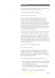
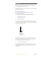
CHC Helical GNSS
Antenna
Other GNSS antennas may however be used ensuring that the antenna
receive the proper GNSS frequencies and operates at either 3.3V or 7.1V
with a signal greater than 40 dB at the antenna port.
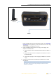
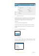
• SYSTEM INSTALLATION DIAGRAM
The typical installation diagram of the CHC X360 GIS Receiver connected
with CHC A220GR GNSS Geodetic Antenna, external power supply and
network cable.