
Use Manual
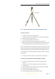
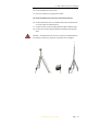
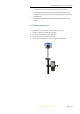
Table Of Contents
- INTRODUCTION
- GETTING STARTED WITH I70
- FRONT PANEL OPERATION
- BASE STATION SETUP AND OPERATION
- ROVER STATION SETUP AND OPERATION
- CONFIGURING THROUGH A WEB BROWSER
- POSITION SUBMENU
- ACTIVITY SUBMENU
- GOOGLE MAP SUBMENU
- TRACKING TABLE SUBMENU
- TRACKING INFO. TABLE SUBMENU
- TRACKING SKYPLOT SUBMENU
- SATELLITE ACTIVATION SUBMENU
- DESCRIPTION
- ANTENNA CONFIGURATION SUBMENU
- REFERENCE STATION SETTINGS SUBMENU
- RECEIVER RESET SUBMENU
- LANGUAGES SUBMENU
- USER MANAGEMENT SUBMENU
- USB FUNCTION SWITCH SUBMENU
- HCPPP SETTINGS SUBMENU
- 1PPS SUBMENU
- LOG SETTINGS SUBMENU
- FTP PUSH SETTINGS SUBMENU
- FTP PUSH LOG SUBMENU
- DATA DOWNLOAD SUBMENU
- IO SETTINGS SUBMENU
- DISCRIPTION SUBMENU
- MOBILE NETWORK SETTING SUBMENU
- EMAIL ALARM SUBMENU
- HTTP SUBMENU
- HTTPS SUBMENU
- FTP SERVICE SUBMENU
- DESCRIPTION SUBMENU
- WIFI SUBMENU
- BLUETOOTH SETTINGS SUBMENU
- RADIO SETTINGS SUBMENU
- BUZZER SETTING SUBMENU
- FIRMWARE INFO SUBMENU
- HARDWARE VERSION
- CONFIG FILE
- SYSTEM LOG DOWNLOAD SUBMENU
- USER LOG
- FIRMWARE UPDATE SUBMENU
- GNSS BOARD UPGRADE
- RADIO UPGRADE
- UPGRADE ONLINE
- GNSS REGISTRATION SUBMENU
- CLOUD SERVICE SETTING SUBMENU

i70 GNSS Receiver User Guide Page 32
5. ROVER STATION SETUP AND OPERATION
Real-Time Kinematic (RTK) operation provides centimeter-level precision by
eliminating errors that are present in the GNSS system. For all RTK
operations, you require both a rover receiver and a source of corrections
from a base station or network of base stations.
The second part of the RTK GNSS system is the rover receiver. The rover
receiver is moved between the points that require measurement or stakeout.
The rover receiver is connected to a base station or to a source of RTK
corrections such as a CORS (Continuous Operational Reference System) or
the CHC APIS service. The connection is provided by:
an integrated radio
an integrated cellular modem
a cellular modem in the controller
This chapter provides the information to help you identify good setup
locations, describes the conventional process to set up the rover station and
the configuring procedure that required for receiving correction data.
5.1. ROVER STATION SETUP GUIDELINES
For good rover operation, observe the following setup guidelines:
Place the GNSS antenna in a location that has a clear line of sight to the
sky in all directions. Do not place the antenna near vertical obstructions
such as buildings, deep cuttings, site vehicles, towers, or tree canopy.
GNSS rovers and the base station receive the same satellite signals
from the same satellites. The system needs five common satellites to
provide RTK positioning.
WARNING – Take care not to touch overhead power lines with the CHC i70
GNSS receiver or the range pole when moving the equipment into position.
Touching overhead power lines may cause electrocution, leading to serious
injury.
GNSS satellites are constantly moving. Because you cannot measure at
a specific location now does not mean that you will not be able to
measure there later, when satellite coverage at the location improves.
To get a fixed position solution with centimeter precision, initialize the
RTK rover receiver. For initialization to take place, the receiver must
track at least five satellites that the base station is also tracking. In a
dual-satellite constellation operation, for example, GPS and GLONASS,
the receiver must track at least six satellites.