
Use Manual
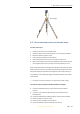
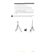
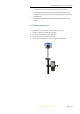
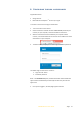
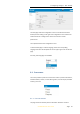
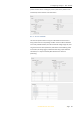
Table Of Contents
- INTRODUCTION
- GETTING STARTED WITH I70
- FRONT PANEL OPERATION
- BASE STATION SETUP AND OPERATION
- ROVER STATION SETUP AND OPERATION
- CONFIGURING THROUGH A WEB BROWSER
- POSITION SUBMENU
- ACTIVITY SUBMENU
- GOOGLE MAP SUBMENU
- TRACKING TABLE SUBMENU
- TRACKING INFO. TABLE SUBMENU
- TRACKING SKYPLOT SUBMENU
- SATELLITE ACTIVATION SUBMENU
- DESCRIPTION
- ANTENNA CONFIGURATION SUBMENU
- REFERENCE STATION SETTINGS SUBMENU
- RECEIVER RESET SUBMENU
- LANGUAGES SUBMENU
- USER MANAGEMENT SUBMENU
- USB FUNCTION SWITCH SUBMENU
- HCPPP SETTINGS SUBMENU
- 1PPS SUBMENU
- LOG SETTINGS SUBMENU
- FTP PUSH SETTINGS SUBMENU
- FTP PUSH LOG SUBMENU
- DATA DOWNLOAD SUBMENU
- IO SETTINGS SUBMENU
- DISCRIPTION SUBMENU
- MOBILE NETWORK SETTING SUBMENU
- EMAIL ALARM SUBMENU
- HTTP SUBMENU
- HTTPS SUBMENU
- FTP SERVICE SUBMENU
- DESCRIPTION SUBMENU
- WIFI SUBMENU
- BLUETOOTH SETTINGS SUBMENU
- RADIO SETTINGS SUBMENU
- BUZZER SETTING SUBMENU
- FIRMWARE INFO SUBMENU
- HARDWARE VERSION
- CONFIG FILE
- SYSTEM LOG DOWNLOAD SUBMENU
- USER LOG
- FIRMWARE UPDATE SUBMENU
- GNSS BOARD UPGRADE
- RADIO UPGRADE
- UPGRADE ONLINE
- GNSS REGISTRATION SUBMENU
- CLOUD SERVICE SETTING SUBMENU

4. Base station setup and operation
i70 GNSS Receiver User Guide Page 30
Slant height
4.3. O
UTPUTTING CORRECTIONS USING EXTERNAL RADIO
For base receiver part:
1. Screw the i70 receiver onto extension pole.
2. Screw the extension pole with auxiliary H.I. tool onto tribrach adaptor.
3. Mount the tribrach onto the tripod.
4. Insert the tribrach adaptor into the tribrach.
5. Level and plumb the receiver over the known (control) point.
6. Measure the height of the base station GNSS antenna by measuring the
slant height from the known (control) point to the auxiliary H.I. tool.
Note – After entered the vertical height from the known (control) point to the
bottom of receiver that you calculated by adding the height of the extension
pole to the height from the known (control) point to the end of auxiliary H.I.
tool, LandStar 7 will calculate the height to the Antenna Phase Center (APC)
automatically.
7. If required, connect the receiver to an external 12 V power supply.
For external radio part (take the CHC DL6 Datalink for example):
8. Connect the Datalink Antenna to the 3 meter Cable for Datalink
Antenna.
9. Connect 3 meter Cable for Datalink Antenna to Datalink Antenna
Mounting Pole.
10. Screw the Datalink Antenna Mounting Pole onto the tribrach adapter.
11. Mount the tribrach onto the tripod.
12. Insert the tribrach adaptor into the tribrach.
13. Set up the Datalink Antenna nearby the base receiver.