
Use Manual
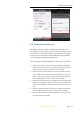
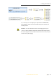
Table Of Contents
- INTRODUCTION
- GETTING STARTED WITH I70
- FRONT PANEL OPERATION
- BASE STATION SETUP AND OPERATION
- ROVER STATION SETUP AND OPERATION
- CONFIGURING THROUGH A WEB BROWSER
- POSITION SUBMENU
- ACTIVITY SUBMENU
- GOOGLE MAP SUBMENU
- TRACKING TABLE SUBMENU
- TRACKING INFO. TABLE SUBMENU
- TRACKING SKYPLOT SUBMENU
- SATELLITE ACTIVATION SUBMENU
- DESCRIPTION
- ANTENNA CONFIGURATION SUBMENU
- REFERENCE STATION SETTINGS SUBMENU
- RECEIVER RESET SUBMENU
- LANGUAGES SUBMENU
- USER MANAGEMENT SUBMENU
- USB FUNCTION SWITCH SUBMENU
- HCPPP SETTINGS SUBMENU
- 1PPS SUBMENU
- LOG SETTINGS SUBMENU
- FTP PUSH SETTINGS SUBMENU
- FTP PUSH LOG SUBMENU
- DATA DOWNLOAD SUBMENU
- IO SETTINGS SUBMENU
- DISCRIPTION SUBMENU
- MOBILE NETWORK SETTING SUBMENU
- EMAIL ALARM SUBMENU
- HTTP SUBMENU
- HTTPS SUBMENU
- FTP SERVICE SUBMENU
- DESCRIPTION SUBMENU
- WIFI SUBMENU
- BLUETOOTH SETTINGS SUBMENU
- RADIO SETTINGS SUBMENU
- BUZZER SETTING SUBMENU
- FIRMWARE INFO SUBMENU
- HARDWARE VERSION
- CONFIG FILE
- SYSTEM LOG DOWNLOAD SUBMENU
- USER LOG
- FIRMWARE UPDATE SUBMENU
- GNSS BOARD UPGRADE
- RADIO UPGRADE
- UPGRADE ONLINE
- GNSS REGISTRATION SUBMENU
- CLOUD SERVICE SETTING SUBMENU
i70 GNSS Receiver User Guide Page 28
4. BASE STATION SETUP AND OPERATION
Real-Time Kinematic (RTK) operation provides centimeter-level precision by
eliminating errors that are present in the GNSS system. For all RTK
operations, you require both a rover receiver and a source of corrections
from a base station or network of base stations.
A base station consists of a receiver that is placed at a known point. The
receiver tracks the same satellites that are being tracked by the rover
receiver simultaneously. Errors in the GNSS system are monitored at the
base station, and a series of position corrections are computed. The
messages are sent through a radio link to the rover receiver, where they are
used to correct the real time positions of the rover.
This chapter provides the information to help you identify good setup
locations, outlines basic precautions that you need to take to protect the
equipment, and describes the conventional process to set up the base
station and the configuring procedure that required for transmitting
correction data.
4.1. B
ASE STATION SETUP GUIDELINES
For good performance, the following base station setup guidelines are
recommended:
Place the GNSS receiver in a location on the worksite where equal
range in all directions provides full coverage of the site.
Place the GNSS antenna in a location that has a clear line of sight to the
sky in all directions. Do not place the antenna near vertical obstructions
such as buildings, deep cuttings, site vehicles, towers, or tree canopy.
The GNSS antenna must have a dear line of sight to the sky at all times
during operation.
Place the GNSS and radio antennas as high as practical. This minimizes
multipath from the surrounding area, and enables the radio to
broadcast to the maximum distance.
Choose the most appropriate radio antenna for the size of the worksite.
The higher the gain on the antenna, the longer the range.
Make sure that the GNSS receiver does not lose power. To operate
continuously for more than a few hours without loss of power at the
base station, provide external power. When you use an external power
supply, the integrated battery provides a backup power supply,
enabling you to maintain continuous operation through a mains power
failure.
Do not locate a GNSS receiver, GNSS antenna, or radio antenna within
400 meters (about 1,300 feet) of transmitters, such as a power radar or