
Data Sheet

EH-ES101
Ehong
®
Professional Bluetooth Solutions Provider page 7 of 14
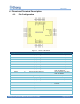
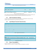
5. Physical Interfaces
5.1. GPIO
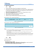
14 IOs are provided. Every IO can program for other function.
All theGP IOs are in high impedance under reset. All the IOs are in high impedance
in low power modes (sleep and standby). If pre-programmed as wake up sources,
pins IO9, IO10 and IO11 are in input pull up.
All the GIOs can programed for an interrupt source. Edge detection or level
detection, and falling/rising or both.
GIO0~GIO8 and GIO14 can program input pull down.
GIO9~GIO11 can program input pull up.
GIO12 can only be General Purpose Input pins (not output).
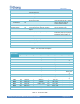
When power for 3.3V, internal Pull resister is:
Name
Description Name
Min
Type
Max
Unit
RPD
Pull-down Value
53
84
144
KΩ
RPU
Pull-up Value
57
81
122
Table 3:Internal Pull for 3.3V
When power for 1.8V, internal Pull resister is:
Name
Description Name
Min
Type
Max
Unit
Digital input and output when 1.8V supply
RPD
Pull-down Value
117
202
363
KΩ
RPU
Pull-up Value
135
211
334
Table 4:Internal Pull for 1.8V
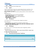
Note:
A. GIO7 can work as BOOT pin. when power on, if GIO7 is high level, CPU will jump to bootloader
mode, and this time can update the firmware by UART.
B. GIO9 and DIO10 can work as SWDCLK and SWDIO. If need debug or download also can use Jlink
OB or ST-LINK.
The IOs programmed to be wake up sources need an external drive according to the selected level
sensitivity. If the wake up level is high level, a pull down drive should be used. If the wake up level is low
level, a pull up drive should be used. If no external drive is applied, IO9, IO10 and IO11 are only sensitive
to low level as they have an internal pull up (activated by default). IO12 do not have an internal pull and
therefore require an external drive.
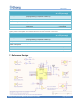
5.2. ADC
2 ADCs are provided.
Main features are:
.
e pins ADC1 and ADC2.
Internal temperature and battery level conversion.