
Product Manual


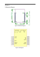


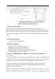
Table Of Contents

3.2 Pin Description
Pin Number
Pin Name
Type
Description
1
GND
P
Ground reference
2
VCC
P
2.1~3.6V
3
-
-
-
4
-
-
-
5
RST
I
Module reset, low active
6
-
-
-
7
DIO10
I/O
SWD DIO
8
DIO9
I/O
SWD CLK
9
-
-
-
10
-
-
-
11
BOOT
I/O
High level active, power on
in normal mode Must be low
12
DTM
I
Factory test mode control
pin, high level effective
13
-
-
-
14
-
-
-
15
BCTS
O
Data entry model
0: the module has data
sending
1: the module sends no data
16
TX
O
UART_TXD
17
RX
I
UART_RXD
18
-
-
-
For more details, refer to BlueNRG-1DataSheet.
.http://www.st.com/content/ccc/resource/technical/document/datasheet/group3/ac/c1/ad/80/54/fa/49/9d/DM0
0262983/files/DM00262983.pdf/jcr:content/translations/en.DM00262983.pdf