SCM-MFD-LC-KIT MFD LIGHTING CONTROLLER KIT INSTALLATION & OPERATION MANUAL W W W. S H A D O W- C A S T E R .
SCM-MFD-LC-KIT OPERATION MANUAL TABLE OF CONTENTS SCM-MFD-LC-KIT BOX CONTENTS ................................................................................................................................3 COMPATIBILITY & OPTIONS ..........................................................................................................................................3 SCM-MFD-LC-KIT OVERVIEW ...................................................................................................................
SCM-MFD-LC-KIT OPERATION MANUAL SCM-MFD-LC-KIT BOX CONTENTS PRODUCT SERIAL NUMBER • SCM-MZ-LC Multi-Zone Lighting Controller • SCM-MFD-BRIDGE Multi-Function Display Bridge • 8 x SS316 Pan Head 8 x ¾" Mounting Screws • Installation & Operation Manual • Warranty and Registration Information You can add your product serial number here for warranty and product registration purposes. The serial number is located on a white label inside the housing of the SCM-MZ-LC.
SCM-MFD-LC-KIT OPERATION MANUAL SCM-MFD-LC-KIT OVERVIEW The Shadow-Caster® MFD Lighting Control Kit (SCMMFD-LC-KIT) includes the Multi-Zone Lighting Controller (SCM-MZ-LC) and the MFD Bridge (SCM-MFD-BRIDGE). The SCM-MZ-LC Lighting Controller supplies fused power connection for up to 4 separate zones of user selectable RGB or RGBW lighting. It can receive an analog music input, and also broadcasts multiple channels of digital commands to other devices on the Shadow-NET® Bus (orange and yellow wires).
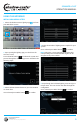
SCM-MFD-LC-KIT OPERATION MANUAL USING THE INTERFACE INITIAL ONBOARDING STEPS 1. Select the Shadow-Caster Lighting app your MFD home screen. icon from 4. Select the number of lighting zones required for your system. Once selected press NEXT button 2. Upon opening the lighting app you should see the welcome screen. Press the NEXT button to initiate the system and proceed through the onboarding process detailed in the following steps. 3. Select the brand/manufacturer of your chosen MFD as shown here.
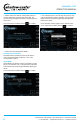
SCM-MFD-LC-KIT OPERATION MANUAL 6. Please make sure that all of the lighting devices on the network are powered and connected. The system will go through and identify everything that is connected. 8. Once all the devices are found by the system, They can be identified by clicking "Identify". All connected lights will turn off, and the light being identified will flash white slowly. Once selected press NEXT button Once identified, set the lights to their desired zones. to confirm.
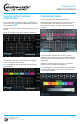
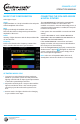
SCM-MFD-LC-KIT OPERATION MANUAL SHADOW-CASTER® LIGHTING HOME SCREEN CONFIGURING ZONES This is the default screen by clicking on the ShadowCaster® app icon after the onboarding process has been completed. Pressing the top button reveals a drop down selection with three options: turn the zone off; select color and brightness control; or select the currently active program. Scenes can now be easily recalled by pressing a scene button. In the zone control box, there are two buttons.
SCM-MFD-LC-KIT OPERATION MANUAL USING SCENES CONFIGURING PROGRAMS A 'Scene' is a way to have all of the zones in your configuration set to a predetermined color, intensity or lighting program. These are accessible by clicking on the PROGRAM button Program . New scenes can be saved and existing scenes can be customized or removed to fit your preferences. MULTI-COLOR CHANGE PROGRAM CONFIGURATION Select Color Sequence pattern.
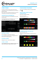
SCM-MFD-LC-KIT OPERATION MANUAL MUSIC SYNC CONFIGURATION Select Type of Sync: Single Lights illuminate on a 'single' selectable color and pulse with the amplitude of the music. Multi Lights cycle through all available colors of at a fixed rate, but similar to Single mode, pulse with the amplitude of the music. CONNECTING THE SCM-MFD-BRIDGE & INITIAL SYNCING The SCM-MFD-BRIDGE is designed to automatically detect the brand of MFD it is connected to and establish a connection.
SCM-MFD-LC-KIT OPERATION MANUAL INSTALLATION SCM-MZ-LC INSTALLATION SCM-MZ-LC POWER REQUIREMENTS Central mounting locations under the helm areas or in the bilges are acceptable. See the Shadow-Caster® wire awg recommendations for detailed calculations. It is very important to have sufficient gauge wire feeds for RGB lighting. 1. Orient the cable glands facing down or to the side so that they do not collect water. 2.
SCM-MFD-LC-KIT OPERATION MANUAL ADDING ADDITIONAL REMOTES AND MULTI-FUNCTION DISPLAYS BEST PRACTICES FOR MITIGATING NOISE ISSUES Additional SCM-ZC-REMOTES can be added to your installation with our Y-cable and 1m, 2m & 4m extension cables. See Optional Parts section below for details. Noise interface is common in systems with RGB lighting controls and amplified stereo systems. The advanced circuitry in the lighting controller does everything possible to protect from this.
SCM-MFD-LC-KIT OPERATION MANUAL TROUBLESHOOTING MFD CONNECTION TROUBLESHOOTING SCM-MZ-LC NOT LIGHTING UP MY SYSTEM IS NOT CONNECTING: When power is first applied to the lighting controller, the box will flash blue very briefly. Remove 4 screws on top of SCM-MFD-BRIDGE. Verify that the blue power light is on. This indicates a bad connection on the 4 pin cable from the lighting controller Verify that the red and green communication lights are coming on and blinking.
AUG21 Designed & Manufactured in Clearwater, FL © 2021 Shadow-Caster® LED Lighting, All Rights Reserved Shadow-Caster® LED Lighting | 2060 Calumet Street. | Clearwater, FL 33765 p: 1+ 727.474.2877 e: info@shadow-caster.com w: shadow-caster.
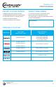
P R O D U C T D A T A S H E E T INTEGRATED MARINE GRADE LIGHTING CONTROL AT YOUR BOATS HELM SCM-MFD-LC-KIT DESCRIPTION Control all of your marine lighting through your vessels touch screen interface and Shadow-Caster®’s easy to use SCM-MFD-LC-KIT (Multi-Function Display – Lighting Controller). Our unique system provides color, brightness, and multiple fade, strobe and music sync modes for up to 6 zones. Simply plug into your system’s network interface and step through the on-screen setup.
P R O D U C T D A T A S H E E T INTEGRATED MARINE GRADE LIGHTING CONTROL AT YOUR BOATS HELM SCM-MFD-LC-KIT C O M PA T I B I L I T Y A N D C A B L E R E Q U I R E M E N T S MANUFACTURER OPTIONAL IP67 SHADOW-CASTER CABLE REQUIRED CABLE FROM MANUFACTURER PN: 010-10550-00 (6ft Cable) Opt: 010-10551-00 (20ft Cable) SCM-MFD-Cable-Garmin Opt: 010-10552-00 (40ft Cable) PN: 010-10580-10 Isolator SCM-MFD-Cable-Navico PN: 000-14552-001 (1.5m Cable) SCM-MFD-Cable-Navico PN: 000-14552-001 (1.
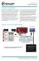
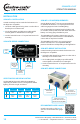
SCM-MFD-LC-KIT & SCM-PD-RELAY-4 with SCR Underwater Lights & 4 Zones of RGB Lights Standard Layout SCM-MZ-LC SCM-MFD-BRIDGE Multi-Zone Lighting Controller HOW TO OPERATE 5 independent on/off switches activate the zones independently of the MFD controls. Multi-Function Display MFD Communications Bridge 12V Power Source When switch is activated, the zone will turn to white. Control: Momentary push button to change color and control brightness. 3.
SCM-MFD-LC-KIT & SCM-SNLC with 6 Switch Inputs, Shadow-NET® Lights & 5 Zones of RGB Lights Standard Layout SCM-MZ-LC-6SW SCM-MFD-BRIDGE Multi-Zone Lighting Controller MFD Communications Bridge Multi-Function Display HOW TO OPERATE 12V Power Source RGB Switches enables RGB Zones 1-4. Shadow-NET Switch enables all lights connected to Shadow-NET®. Control Switch momentary push button to change color and control brightness. SCM-SNLC (Includes 10A Fuse) MFD control will override all switches. 3.
SCM-MFD-LC-KIT with 2 Switch Inputs, Shadow-NET® Lights & 4 Zones of RGB Lights Standard Layout SCM-MZ-LC-2SW SCM-MFD-BRIDGE Multi-Zone Lighting Controller HOW TO OPERATE RGB Switch enables RGB Zones 1-4. Multi-Function Display MFD Communications Bridge 12V Power Source Control Switch Press and hold for brightness. Press to start/ stop color rotation. Shadow-NET Lights all controlled via MFD. 3.5mm Female Audio Jack for music sync MFD control will override all switches.
SCM-MFD-LC-KIT with 3 Switch Inputs, Shadow-NET® Lights & 4 Zones of RGB Lights Standard Layout HOW TO OPERATE SCM-MZ-LC-3SW SCM-MFD-BRIDGE Multi-Zone Lighting Controller RGB Switch enables RGB Zones 1-4 to white color. Shadow-NET Switch enables all lights connected to Shadow-NET®. Multi-Function Display MFD Communications Bridge 12V Power Source Control Switch is a momentary input to set brightness and change color. 3.5mm Female Audio Jack for music sync MFD control will override all switches.
SCM-MFD-LC-KIT with 6 Switch Inputs, Shadow-NET® Lights & 4 Zones of RGB Lights Standard Layout HOW TO OPERATE SCM-MZ-LC-6SW SCM-MFD-BRIDGE Multi-Zone Lighting Controller Multi-Function Display MFD Communications Bridge RGB Switches enables RGB Zones 1-4. Shadow-NET Switch enables all lights connected to Shadow-NET®. 12V Power Source Control Switch momentary push button to change color and control brightness. MFD control will override all switches. 3.
SCM-MFD-LC-KIT with Shadow-NET® Lights & 4 Zones of RGB Lights Standard Layout HOW TO OPERATE SCM-MZ-LC SCM-MFD-BRIDGE Multi-Zone Lighting Controller Multi-Function Display MFD Communications Bridge All configuration and control of system will be done through the MFD user interface. 12V Power Source RECOMMENDED WIRE GAUGES 3.5mm Female Audio Jack for music sync Scan the QR Code or click here to view our recommended wire gauge chart.