
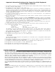
Installation manual


4
INSTALLATION
Printer Connections
The following printers can be used with MLR2-DG:
Model Column DIP Switch Settings
Width 1 2 3 4 5 6 7 8
Citizen 40/80 n/a n/a n/a n/a n/a n/a n/a n/a
180D
Epson 40/80 n/a n/a n/a n/a n/a n/a n/a n/a
LQ-570+
Okidata 40/80 off off off off on off on off
ML 182 Turbo
Okidata 40/80 off off off off on off on off
ML 182 Plus
Okidata 40/80 on off off off on off on off
ML 184 Turbo
Panasonic 40/80 n/a n/a n/a n/a n/a n/a n/a n/a
KX-P1150
Star 40/80 n/a n/a n/a n/a n/a n/a n/a n/a
NX-1000
Star 40 on on on on on on on on
DP8340
Tandy DMP-206 40/80 n/a n/a n/a n/a n/a n/a n/a n/a
For the
Star DP8340Star DP8340
Star DP8340Star DP8340
Star DP8340 (Sur-Gard part # DCDP8340), the SG-
1220B power supply should be used (Sur-Gard part number
XP1220) The SG-1220B is a 12V 2A power supply housed
in a metal case with a tamper switch. It requires one 12VDC
sealed rechargeable battery (6 to 25 Ah rating) and one
16VAC 40VA Class 2 wire-in transformer (Frost FTC4016 or
equivalent).
Connect the parallel printer to the MLR2-DG printer output
port using a parallel printer cable.
IMPORTANT: Do not use a printer cable which has
only 1 common ground wire.
Computer Connections
• Connect the computer to the MLR2-DG RS-232 port using
a serial cable to COM1.
IMPORTANT: Do not use a null modem cable.
Receiver RS-232 Computer RS-232 Computer RS-232
25 pin connector 25 pin connector 9pin connector
11
22 3
33 2
77 5
Telephone Line Connections
• With 6-pin modular cables, connect each line module
output to its corresponding telephone line.
Grounding
• For maximum resistant to static and electrical noise, the
19" rack frame should be connected to earth ground
through the AC utility box.
Power Supply
• Ensure that all electrical connections are made correctly.
After verifying all connections, connect the RED and BLACK
leads to a 12VDC sealed rechargeable battery. Be sure
to observe polarity when connecting the battery. When
the battery is connected, test the system under battery
power only.
• If a separate DC input is used to power the LCD
backlighting during AC power failures, connect it to the
BLGT terminal. It must be a listed Fire-Protective Signalling
Mounting the Receiver
• Install the MLR2-DG in a closed 19" rack or cabinet with a
locking rear access door. Cover all unused spaces with
blank metal plates. The LCD screens on the receiver are
designed to be viewed below eye level. If the unit must be
mounted where the screens are above eye level, angle the
unit downwards to improve visibility. The following items
can be supplied for a complete installation:
Stand-up Unit (61.25" tall up to 14 telephone lines)
Part # MLR2A-CL
PartPart
PartPart
Part
Rack
Door with lock and
ventilation
Blank plates 21" (2)
Blank plate 5.25" (3)
Screws
Washers
Clipnuts
FROST 16V 75VA
transformer
(RTFR7516)
AC Utility Box
AC Cable Clamps (2)
8' Battery Cables
18 gauge 3-conductor
AC Cable
Note: If 14 telephone lines are not used, cover each
unused location with a blank plate
Desk-mount Unit (28" tall up to 14 telephone lines)
Part # MLR2A-CM
PartPart
PartPart
Part
Rack
Louvred door back
plate
Blank Plate 1.75"
Back Plate 7"
Blank Plates 5.25 (4)
Screws
Washers
Clipnuts
16V 75VA Transformer
AC Utility Box
AC Cable Clamp for 3/8" cable N/A
8' Battery Cable
18 gauge 3-conductor AC Cable
Note: If 14 telephone lines are not used, cover each
unused location with a blank plate