
Installation manual


3
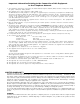
Direct Connect Testing Wiring Diagram Shown with a Control Panel
QUICK START
Power Up
When power is applied, the receiver will beep and will
indicate one or more trouble conditions on the LCD message
screen. If the Line Cards do not have telephone lines
connected, the DRL2A modules will beep and their “ALARM”
lights will FLASH.
Press the flashing [ACK] button to silence the buzzer. If
there is no computer or printer connected, a trouble message
will be displayed on the CPM2 LCD and the “ACK” light will
FLASH. Press the [ACK] button to silence the CPM2 buzzer.
Operation with Default Program
Without any changes to the factory default programming,
the receiver operates as follows:
• The master ID password is “CAFE”.
• Answers incoming calls on the first ring
• Sends 2300 Hz as the first handshake
Sends 1400 Hz as the second handshake
Sends dual tone as the third handshake
Sends SIA FSK tone as the fourth handshake
Sends ITI tone as fifth handshake
Sends 1600 Hz as sixth handshake
• Receives all Communication Formats, except for:
3/2, 4/1 express, 4/2 extended and VONK
The above formats can be manually selected, but may
conflict with more commonly used formats.
• Signals will be displayed on the Line Card LCD as they
are received. The signals are then sent to the parallel
printer and computer connected to serial port COM1.
The default event codes described in the “DRL2A Library
Decoding and Event Codes Table” will be used with the
Sur-Gard RS-232 Communication Protocol to send signals
to the computer, if connected.
• If a computer is not connected, press the [ACK] button
on the CPM2 module to silence the buzzer. The time and
date of the Acknowledgment will be printed.
Receiver Setup and Operation Without
Programming
Unpacking
Carefully unpack the receiver and inspect for shipping
damage. If there is any apparent damage, notify the carrier
immediately.
Introduction to Operation
Refer to the following sections of this manual for an overview
of the operation of the DRL2A Digital Receiver Line Card
and the CPM2 Central Processing Module:
• DRL2A General Information
Features
Installation
Controls and Display
• CPM2 General Information
Controls and Display
Cold Start-up
If the receiver is to be used with a computer and central
station automation software, refer to “MLR2-DG Computer
Interface”
Bench Testing
It is suggested that the receiver be tested before actual
installation. Become familiar with the connections and setup
of the unit on the work bench to make final installation
easier.
The following items are required:
• 16VAC transformer
• 2 telephone lines
• One or more dialers or digital dialer control panels
Direct connection testing without the use of telephone lines
is possible by using the ring simulator switch input
connections on the back of the receiver
Dialers and control panels using an optocoupler phone
line interface will require a connection method providing a
DC current for direct connection testing.