
Operating instructions


9
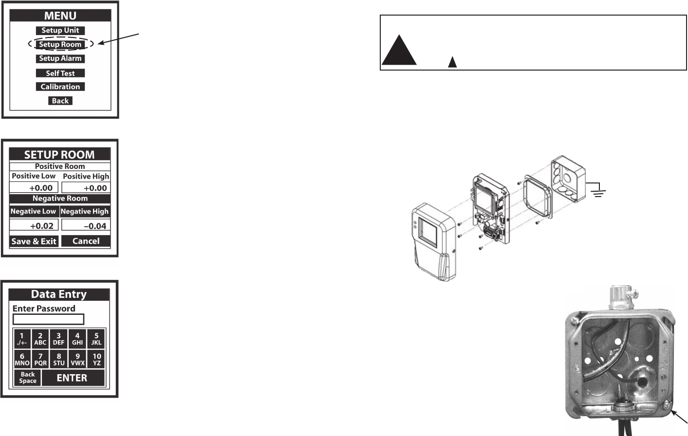
3.0 Mounting and Wiring
3.1 Mounting
For 120/240 VAC Version, only
CAUTION: Do not open or remove SRPM cover (tool required) with input
power applied unless performed by a licensed electrician. “Hazardous Live” voltage
is present at connector J3 when power is applied. Please observe the warning
symbol ( ) near the J3 power connector.
The Setra Room Pressure Monitor is designed to be mounted on a standard
double gang metal electrical box using a 4 x 4 inch plaster ring adaptor.
Remove the SRPM cover and mount the baseplate to the plaster ring adaptor
using (4) 6-32 1/2 inch long mounting screws, see Figure 2. Note: The plaster
ring external mounting face needs to be positioned flush to recessed, relative
to the surface of the wall. Also note the orientation of the 4 mounting screws in
the plaster ring, the plaster ring is rotated 90° from conventional mounting.
3.2 Wiring Electrical box (rough in)
Pre-wire electrical box with power (24 VAC or
120/240 VAC depending on SRPM model ),
and provide grounding to the electrical box
and plaster ring adaptor. Note: For CSA Safety
Certification it is necessary to ground the metal
electrical box to building earth ground. The
safety ground path consists of the (4) 6-32
x 1/2” metal screws that connect the RPM
metal base to the 4” x 4” metal plaster ring. The
plaster ring is grounded to the 4” x 4” electrical box
by 2 mounting screws.
Electrical Box
4 x 4 inch Plaster Ring
(Rotated 90°)
SRPM Metal Base
SRPM Cover
Figure 4: 4” x 4” Electrical Box
Power leads and wiring should be 14 to 22 AWG braided wire. 18 AWG braided
wire is recommended for wiring J3 power connector to SRPM (see J3, Figure 2).
For 120/240 VAC the hot wire connects to H and neutral to L.
Figure 3: Mounting the SRPM
!
!
20
7.4.1 Setup Room Operation
Monitor either “protective” positive room static
pressure or “isolating” negative room static
pressure.
7.4.2 Entering Data
Press lightly or tap Positive Room or Negative
Room button. Background of selection will
change from clear to black, then enter high
and low limits as follows:.
Simply press lightly (or tap) either the “Positive
Room” or “Negative Room” box to activate the
“Data Entry Screen” (see 7.4.3.), then proceed to
enter the low and high limits of the room pres-
sure to be monitored. Save and Exit.
7.4.3 Data Entry Screen
Enter numbers by pressing each key in sequence
until the desired character is displayed in the data
entry box above the keypad. (Note: The cursor will
blink for one to two seconds then stop and display the
character.) Erase any mistakes by using the “Back
Space” key. When finished entering data, “Press En
-
ter” key to return to SETUP UNIT screen, press “Save
and Exit” to return to MAIN MENU, then press “Back”
to return to PRESSURE MONITORING SCREEN.
7.4 SETUP ROOM SCREEN
Example:
Enter number 3, press (or tap) 3/DEF key once
Enter the letter T, press (or tap) the 8/STU key three times in succession.
Note: Use the eraser end of a pencil or back-end of a pen to press (or tap) box on screen to
increase accuracy of inputs.
.
Press to Access Screen
Mounting Screws (x2)