
Operating instructions


13
1 V Out 0 to 5, 0 to 10 VDC
2 C Out 4 to 20 mA
3 Common
Figure 11: Analog Output (J5)
6.0 Electrical Installation
6.1 Analog Output (J5)
SRPM can be configured as current (4 to 20 mA) or voltage (0 to 5 or 0 to 10 VDC).
Voltage output pin 1, Current output pin 2, Common pin 3. Note. No external
excitation is required.
16
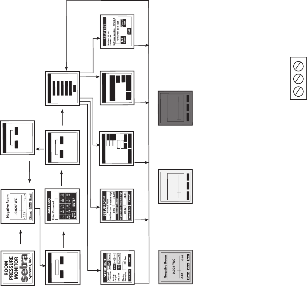
Menu Tree
(Shown with Password Entry)
Pr
essure Monitoring
Screen
WelcomeScreen
Main Menu
Screen
Data Entry Sreen
Passw
ord
Entere
d
Correc
tly
Normal, Wa
rning, and Alarm C
ondition Screens
Pressure is normal,
the
screen is Green
Pressure is normal and do
or is
open, the screen is
Y
ello
w
Pressure falls outside of
preset limits (alarmed state),
the screen is Red
S
etup Unit Screen
Enter Pa
rameters
Selec
t “Save” to exit
.
Setup Room Screen
Enter Pa
rameters
Selec
t “Save” to exit
.
Alarm Setup Screen
Enter Parameters
Selec
t “Save” to exit
.
Calibration Screen
Apply Parameters or
“Restore
Fact
ory Setting”.
Self
Test Screen
Test Alarm
LOGIN
Enter P
asswor
d
OK
Cancel
Usr!
Wrong P
asswor
d
Entere
d,
Re-ente
r
the P
assw
or
d
LOGIN
Enter P
assw
or
d
OK
Cancel
L
OGI
N
Enter P
asswor
d
OK
Canc
el
User!
MENU
Setup Unit
Setup Room
Setup
Alar
m
Self Test
Calibration
Back
MENU
CALIBRATION
Negative Room
Apply Zero
Pressur
e
Apply Full Scale
Pressur
e
-0.026
“W
C
ZER
O
SP
AN
Restore
Factory Setting
Exit
Pa
ssword No
t
Entered Correc
tly
Negativ
e Room
–0.021” WC
-0.02
-0.04
Silence
Menu
Reset
Door Open
Negative Room
–0.001”
WC
-0.02
-0.04
Silence
Menu
Reset
Door Open
Wr
ong password
entered or Number
of Tries Ex
ceed the
Maximum Number
of Tries. Return to
Pressure Monitoring
Screen
MENU
ALARM SETUP
Latch Alar
m
Audible alar
m
Door A
larm Input
Yes
Ye
s
Ye
s
No
No
No
Mute Time Out
Secs
Alarm
Dela
y
Secs
Volume
4
Cancel
Save & Exi
t
Up
Down
30
10
Login Sreen
Menu Button Pressed