
Operating instructions


11
4.0 Model SRAN Room Annunciator Installation
4.1 Alarm Relay Output
The Single Pole Double Throw (SPDT) relay output can be used for remote signal-
ing of alarm condition. A form “C” contact rated at 1A is available. Connect to J4,
Pins 1 and 4.
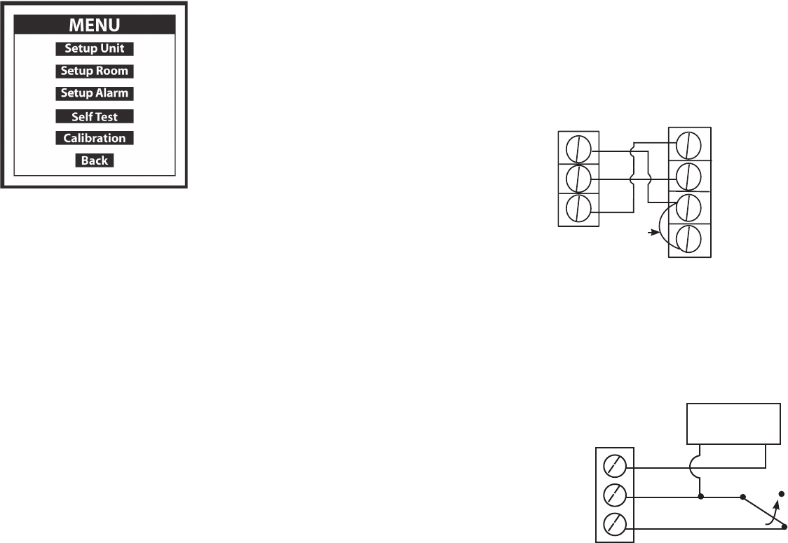
4.1.1 Model SRAN Remote Annunciator Wiring
(see Figure 8 below or Figure 2, pg. 8)
Remote Annunciator Connector (J1), SRPM Connector J4:
Connect pins 1 & 2 (short) and then connect pin 2 (+15 V Exc.), pin 3
(Ground, pin 4 (Annunciator Trigger).
4.1.2 Non-Setra Remote Annunciator
The SRPM can drive other annunciators that are powered by a 15V sup
-
ply, 50 mA max., and accept a 15V trigger. If purchased separately, the
SRAN can also be driven as shown in Figure 9.
+15 VDC Excitation A1
Ground A2
+15 VDC Trigger A3
N.C.
(No Alarm)
N.O. (Alarm)
J1
Jumper
P4 (Annunciator Trigger
P3 (Ground)
P2 (+15 VDC Excitation)
P1 (Relay N.O.)
+15 VDC Excitation A1
Ground A2
+15 VDC Trigger A3
J1: SRAN
J4: SRPM
Power Supply
15 VDC
– +
Figure 8: Model SRAN Wiring
Figure 9: Remote Annunciator Wiring
18
Button Description
Setup Unit Setup password, output, engineering
units, and display averaging
Setup Room Setup high and low pressure limits to
monitor positive or negative room
Setup Alarm Setup latch alarm, audible alarm, door
alarm input, mute time out, alarm delay,
and volume
Self Test Identifies product model and software version.
Verifies SRPM operation and alarm sound level
and setup
Calibration Perform zero and span calibration
Back Returns to monitoring screen
7.2 MAIN MENU SCREEN