
Operating instructions


10
3.3 Attaching Pressure Tubing
Typically a Room Pressure Snubber (RPS) is
installed in the monitored room. Attach pressure
tubing as follows:
1. ) Connect the 1/4 inch O. D. tubing (Figure 5)
from the RPS to the 4” x 4” electrical box for the
SRPM by pushing the 1/4 inch tube onto one end
of the barbed, male to male, tube adaptor, then
push the silicone tube (supplied) onto the other
end (see Figure 6). Thread the tubes, with installed
adaptor, through the conduit opening at the bot-
tom of the electrical box (see Figure 7).
2. ) Next push the open end of the silicone tub-
ing onto the removable SRPM header (H1), port
labeled “+”(see Figure 7).
Note: The header is an Electro-Pneumatic (EP)
assembly. “+” indicates (Positive) pressure, and “-”
indicates (Negative or Reference) pressure.
3. ) For the most pressure stable operation an
RPS installed in the reference pressure area is also
recommended. In this case, install the RPS in a hall-
way or anteroom. Plumb to the SRPM in the same
way as “+” pressure, except plumb the tube to the
“-” port on Header H1. Tighten swivel
fittings on the EP assembly if they become loose.
Figure 5: Room Pressure
Snubber (RPS)
1/4” O.D.
Tubing
Electrical Box
Silicone Tubing
RPS Tubing
SRPM Header H1
Figure 6: Silicone & RPS Tubing
connected by barbed Male to
Male Tubing Adaptor
Figure 7: Example of
Completed Tube Installation
19
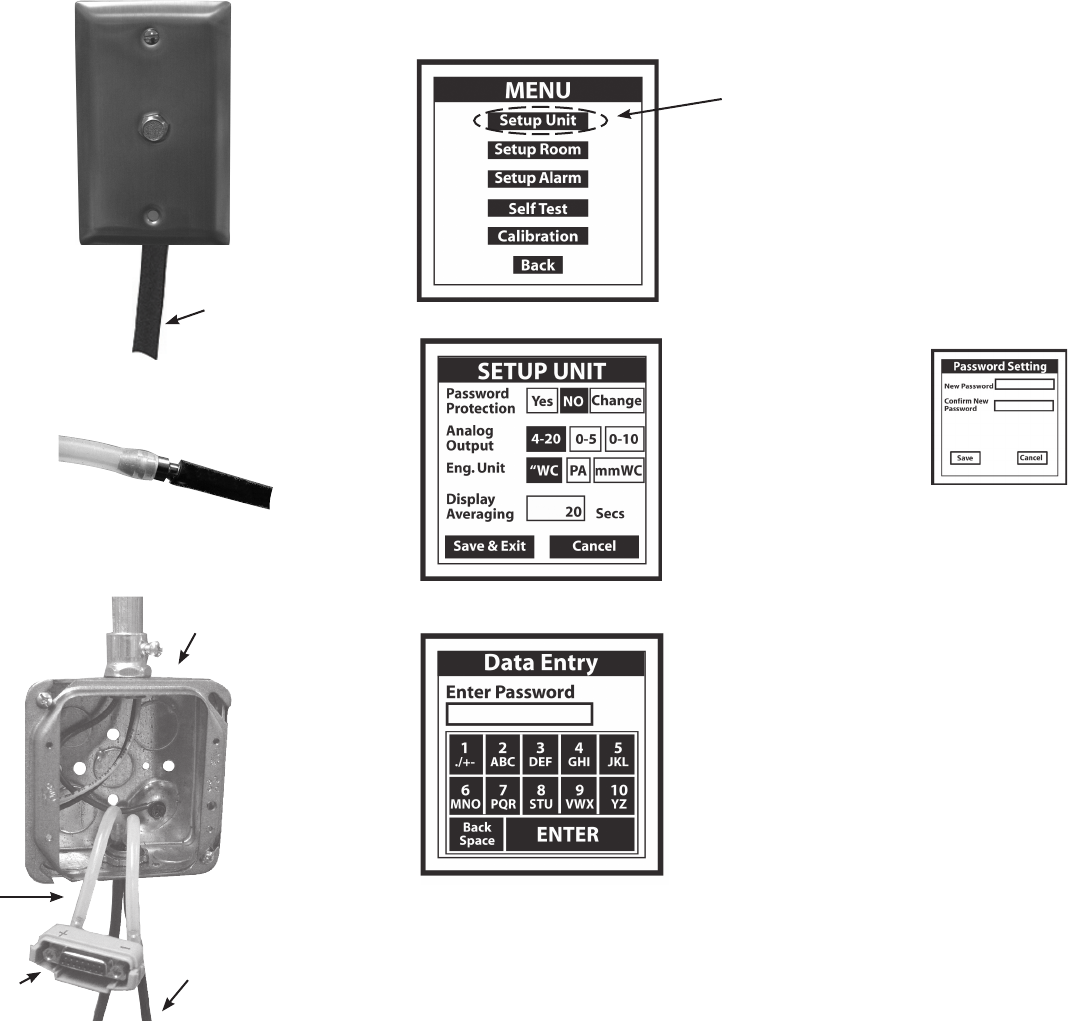
7.3.1 Setup Unit Operation
Press (or tap) button to select an output or engineer-
ing unit. Selected button background will change from
clear to black.
7.3.2 Entering Data
7.3.2.1 Password Protection
Lightly pressing (or tapping) the
“Yes” button activates the “Data
Entry Screen” (see 7.3.3 to enter
your password. ) Enter password,
then press “Enter”. “Password Set-
ting Screen” will pop-up, enter new
password, enter password again to
confirm, then press “Save”.
(See MENU TREE, page 16 for password entry opera-
tion.)
7.3.2.2 Display Averaging
Lightly pressing (or tapping) the box activates the
“Data Entry Screen” (see 7.3.3). Enter from 0 to 60
seconds. Display averaging affects the analog output.
Increase display averaging time to “Smooth” the pres-
sure readings.
7.3.3 Data Entry Screen
Enter letters or numbers by pressing each key in
sequence until the desired character is displayed in
the data entry box above the keypad. (Note: The cursor
will blink for one to two seconds then stop and display
the character.) Erase any mistakes by using the “Back
Space” key. When finished entering data, “Press Enter”
key to return to SETUP UNIT screen, press “Save and
Exit” to return to MAIN MENU, then press “Back” to
return to PRESSURE MONITORING SCREEN.
7.3 SETUP UNIT SCREEN
Press to Access Screen
Example:
Enter number 3, press (or tap) 3/DEF key once.
Enter the letter T, press (or tap) the 8/STU key three times in succession.
.
Note: Use the eraser end of a pencil or back-end of a pen to press (or tap) box on screen to
increase accuracy of inputs.
Password Setting Screen