SERVOSILA SC-25 Brushless Motor Controllers Programming Guide Revision C www.servosila.com/en/motion-control 1 www.servosila.
Table of Contents Introduction......................................................................................................................................4 Network Architecture.......................................................................................................................6 CAN Network.............................................................................................................................6 USB-to-CAN Gateway + CAN Network...................................
Serial Port Settings....................................................................................................................21 Starting SLCANd daemon under Linux....................................................................................22 Sample Projects (C++)...................................................................................................................23 3 www.servosila.
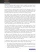
Introduction Servosila SC-25 Brushless Motor Controllers provide an a CANopen control interface, and an open USB 2.0 interface, a virtual COM port, for receiving commands from a control computer/PLC as well as for sending telemetry back. No proprietary drivers or SDKs are needed to connect the Servosila controllers to a Linux or a Windows 10/8 computer.
In general, user software for a control computer/PLC can be developed in any language that supports either Linux SocketCAN API or read/write operations for virtual COM ports on Windows 10/8 or Linux. This includes C/C++, Qt, Java, Python, MATLAB, LabView, and many other languages and packages. The brushless motor controllers come with a graphical software tool called “Servoscope”.
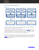
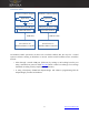
Network Architecture CAN Network Servosila SC25 Brushless Motor Controllers are designed to connect to a control computer (PLC or Autopilot) via a CAN bus network. The control computer needs to have a physical CAN bus interface or some sort of an interface adapter to connect to the controllers this way. CAN Control Computer / PLC Brushless Motor Controller 1 Brushless Motor Controller 2 ...
Up to 16 controllers chained via their CAN bus ports can be controlled by the same PC/PLC using the built-in USB-to-CAN routing function. The limit is mainly due to throughput of a USB port of the Servosila controller that acts as a USB2CAN dongle in addition to driving a motor. Unique Node ID Each brushless motor controller is assigned a unique Node ID, an integer between 1 and 126.
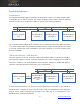
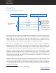
Application Programming Interfaces Linux APIs Linux Control Computer Linux Control Computer Linux Control Computer Application Application Application C/C++ API C/C++API Linux SocketCAN API Linux SocketCAN API CAN bus hardware SLCANd (driver) CAN bus cable Servosila SC-25 Brushless Motor Controller Text File API /dev/ttyAC** USB cable USB cable Servosila SC-25 Brushless Motor Controller Servosila SC-25 Brushless Motor Controller Linux SocketCAN API can be used to develop software that se
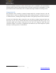
Windows APIs Windows Control Computer Windows Control Computer Application Application Text File API API Virtual Serial (COM) port Third-party proprietary API USB CDC driver CAN bus hardware USB cable Servosila SC-25 Brushless Motor Controller CAN bus cable Servosila SC-25 Brushless Motor Controller As Windows 10/8/7 systems do not have such a unified CANbus API, the ways for a control system’s software running on Windows to interact with Servosila brushless motor controllers include: • either
Message Flows Sending COMMANDS to devices Control Computer / PLC Brushless Motor Controller command Continuous stream of commands command command ... The interval between consecutive commands should be less than the controller’s heartbeat timeout period, a configurable parameter. Otherwise, the controller assumes that there is a failure, and halts the motor as a safety measure.
Sending the commands too often might flood the network with unwanted messages, thus there is a configuration parameter that controls the trade-off. The flow of commands described in this section is applicable to both CAN and USB interfaces. The format of the command messages is described later in this document. The format follows CANopen standard (RPDO).
Fault Acknowledgment Whenever an internal fault is detected by a Servosila SC25 Brushless Motor Controller (e.g. an encoder error), the controller automatically powers off the motor as a safety measure, raises one or more "Fault Bits" flags in telemetry, and starts waiting for a "Reset" command to come from a parent control system. Until a "Reset" command comes, the controller ignores all other commands received from the parent control system. All configuration management functions 4 keep working as usual.
Control Computer / PLC Brushless Motor Controller Read Request (index, subindex) Read Response (index, subindex, value) To identify a parameter of interest, the control computer uses an [Index:Sub-Index] pair of numbers. A list of all parameters, their indices, sub-indices and data types is given in a Servosila Device Reference document. If the device does not find the requested parameter (e.g. an invalid index or sub-index), the device replies with an error message.
Encoding and Decoding General message structure CAN ID (11 bits) Node ID + COB ID Payload (8 bytes, binary) 0 1 2 3 4 5 6 7 Example CAN ID computation: if Node ID is 5, and COB ID is 0x200, then CAN ID is 0x205 All types of messages consist of just two components, a CAN ID and a binary Payload. • CAN ID is an addressing mechanism in a CAN bus network. CAN ID is defined as a sum of Node ID and a COB ID.
Encoding COMMANDS CAN ID (11 bits) Node ID + COB ID Payload (8 bytes, binary) 0 1 2 3 4 5 6 7 Command-specific payload section Most commands have parameters. Those parameters are encoded in this section. Position of each parameter and parameter’s data type are listed in Servosila Device Reference document. For example, “Electronic Speed Control” command has a single parameter called “Speed” of FLOAT32 type, encoded starting from byte 4 of the Payload.
Decoding TELEMETRY CAN ID (11 bits) Node ID + COB ID Payload (8 bytes, binary) 0 1 2 3 4 5 6 7 Telemetry payload section Each of telemetry messages carries parameters (data) in the Payload array. The parameters of each of the telemetry messages, their data types and positions in the Payload are listed in Servosila Device Reference document. COB ID There are just 4 telemetry COB IDs: 0x180, 0x280, 0x380, 0x480. COB ID of a telemetry message tells how to decode it.
Encoding a READ REQUEST CAN ID (11 bits) Node ID + COB ID Payload (8 bytes, binary) 0 1 2 3 4 5 6 7 Sub-Index Each telemetry or configuration parameter has a Sub-Index defined in Servosila Device Reference document for that particular parameter. For example, a telemetry parameter “Torque” has sub-index = 0x02 Index Each telemetry or configuration parameter has an Index defined in Servosila Device Reference document for that particular parameter.
Decoding a READ RESPONSE CAN ID (11 bits) Node ID + COB ID Payload (8 bytes, binary) 0 1 2 3 4 5 6 Value 7 A data type of the value is defined in Servosila Device Reference document. Sub-Index Each telemetry or configuration parameter has a Sub-Index defined in Servosila Device Reference document for that particular parameter.
Data Types Data Type Size in bytes Comments BOOL 1 Same as UINT8. UINT8 1 Byte. INT8 1 Signed byte. UINT16 2 Little-endian format. INT16 2 Little-endian format. UINT32 4 Little-endian format. INT32 4 Little-endian format. FLOAT32 4 IEEE 32-bit floating point value. Little-endian format. FLOAT16 2 This is a proprietary floating number format defined by Servosila. See a description below. FLOAT16 The FLOAT16 type is transmitted the same way as INT16, a signed integer.
List of applicable COB IDs COB ID (hex) Used to transmit Direction 0x200 commands Control Computer → Device 0x300 commands Control Computer → Device 0x400 commands Control Computer → Device 0x500 commands Control Computer → Device 0x180 telemetry Device → Control Computer 0x280 telemetry Device → Control Computer 0x380 telemetry Device → Control Computer 0x480 telemetry Device → Control Computer 0x580 read responses Device → Control Computer 0x600 read requests Control Comput
SLCAN Text Protocol Format of an SLCAN text message CAN ID (11 bits) Node ID + COB ID Payload (8 bytes, binary) 0 1 2 3 4 5 6 7 t2058200000000000C842[CR] Every SLCAN message ends with a carriage return (CR) symbol (ASCII 0xD). The Payload is encoded as a string of 16 hexadecimal symbols (ASCII). Every byte of the original binary 8bytes payload is represented by 2 symbols. So, there are 8*2 hexadecimal symbols in the payload sub-string. Number of bytes in the original payload.
Starting SLCANd daemon under Linux Linux’s pre-packaged SLCANd daemon allows using Linux SocketCAN API with USB interface of Servosila SC-25 Brushless Motor Controllers. Otherwise, the daemon is not required. Use the following commands to start SLCANd daemon under Linux: root@debian# slcand /dev/ttyACM0 can0 root@debian# ip link set up can0 22 www.servosila.
Sample Projects (C++) Project Name OS Interface Language Type of Dependencies application Description canbus-esc-command Linux CAN C++ command line none The sample shows how to send an Electronic Speed Control command via CAN bus (Linux SocketCAN API). canbus-telemetry Linux CAN C++ command line none The sample demonstrates how to receive and decode telemetry messages coming via CAN bus.
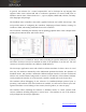
Figure 1: Screenshot of MotorControlGUI, an example project written in C++ with Qt library. The sample program runs on both Windows and Linux. The source code of the application is freely available for modification, reuse or distribution. 24 www.servosila.
Servo drives designed around SERVOSILA SC-25C brushless motor controllers YouTube: http://www.youtube.com/user/servosila www.servosila.com/en/motion-control 25 www.servosila.