
Operator`s manual


MAINTENANCE
RC12 03/09 Maintenance Section 5-6
© 2009 Alamo Group Inc.
MAINTENANCE
Once both pulley and hub start seperating, attempt to move assembly on shaft.
Never hammer edge of pulley which may crack. To move assembly, a soft blow hammer
may be used on bushing only.
If the pulley is free and the bushing is still tight on shaft, it may be necessary to wedge a screwdriver in saw slot
of bushing to loosen and move hub.
Do not apply excessive force which may split bushing.
Never apply lubrication to threads or mating surfaces when assembling pulley and bushing.
After correctly locating hub and placing key in shaft keyway, move pulley into position over
taper hub and align tapped holes with through holes in hub. Install all mounting cap screws . Carefully tighten
the cap screws alternately and progressively until tapers are seated. Check alignment of pulley and proceed to
carefully tighten to 40 ft lbs torque. Maximum torque should be reached on each individual bolt only twice in the
consecutive tightening.
CUTTER SHAFT AND BEARING REMOVAL
Cutter Shaft Bearing Removal - Mnt-FL-0041
OUTER CUTTER SHAFT BEARING REMOVAL
• Remove belt; disconnect tension rod; loosen adjustment tube pivot points bolts; rotate assembly toward
deck; remove belt.
• Remove lower sheave: see Maintenance 5-4.
• Disconnect grease line.
• Remove both set screws from bearing lock collar. (NOTE: set screws allign with dimples in shaft), set
screws are lock tightly in place.
• Place floor jack under cuttershaft inside end plate to support weight of shaft.
• Remove dirt, debris,and paint from shaft.
• Unbolt bearing and mount plate assembly by removing four outer bolts. (Mnt-FL-0041 - item 11)
• Remove bearing from mount plate.
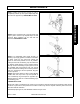
INSTALLATION
Clean all debris from shaft. Attach bearing (1) to bearing plate (2) using four 5/8" bolts (3) and locknuts (4).
Slide assembly over shaft and align set screws with dimples in shaft. Install lock collar and apply thread locking
compound to set screws and tighten in place. Attach bearing assembly and plate with outer four 5/8" bolts.
Install belt as outline in Maintenance 5-4.