
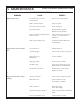
Technical data

- 27 -
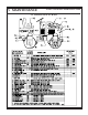
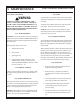
3. MAINTENANCE
WolfPac 3100/WolfPac 3100R/WolfPac 3100D
Refer to illustration below for assembly information
travel 1 1/8.
3.24 PARKING BRAKE
It should take a force of 25-35 pounds, applied at the
end of the brake lever, to apply the brake lever. The
brake should prevent the roller from moving when
applied. Turn knob on brake lever to adjust. Clockwise
will increase the force, counterclockwise will decrease
it.
3.25 WATER TANK
The water tank is polyethylene to prevent corrosion.
The water tank holds 40 US gallons. Dirty water will
clog the sprinkler bars. If the water tank is subject to
freezing temperatures, all the water lines and the water
tank must be drained by drawing through sprinkler
tubes or removing the cover at the rear of the machine
to gain access to the water tank, flush and drain plug.
3.26 SPRINKLERS
The sprinkler tube assemblies are PVC to prevent
corrosion. The sprinkler tube assemblies are equipped
with a clean out plug for cleaning when required.
3.27 SCRAPER MAINTENANCE/ADJUSTMENT
Scrapers must make uniform contact across entire width
of drum to ensure even application of water from the
sprinkler system. Tension is adjusted by sliding slotted
brackets in or away from drum surface.
Loosen the 2 bolts that hold item to the frame
and slide away or towards the drum and
retighten.
3.28 ECCENTRICS
When vibratory compaction is necessary, engage
eccentrics by actuating eccentric switch. Operator may
vary the frequency and therefore the centrifugal force
by varying engine RPM. Eccentrics should be turned
off whenever the roller is stopped, or stopped to change
direction. Do no run the eccentric on any non-yielding
surface, such as concrete or aged asphalt.
NOTE: Test vibration with front drum on soft ground.
Run engine at full RPM to obtain vib speed 3900
+
100check per below.
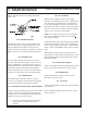
To check vibration with a vibrotach, place the vibrotach
on the vibrating member surface, record reading when
the wire reaches maximum movement. (Vibrotach P/N
37891). Adjust engine RPM to obtain proper eccentric
speed.
When checking vibration with a strobe light, place a
horizontal line on the vibrating member surface. Check
with strobe light-record reading when the line reaches
minimum movement.
3.29 ENGINE MOUNTING
Check weekly-tighten all mounting hardware for proper
torque, refer to parts illustrations for proper torque.
3.30 HARDWARE
Inspect all hardware for tightness. Refer to parts
illustrations for proper torque.
3.31 LOCTITE
Loctite 262 threadlocker is required to prevent hardware
from loosening.
Refer to exploded diagrams and parts list for * where
loctite is required.