Server Technology Inc.
Table of Contents Introduction 5 About this Guide 6 Product Overview 7 Intelligent Power Module (IPM) 8 Power On/Off +Aux control unit 9 A Sample Session, Power-ON Mode 11 Installation Installing the IPM 12 Installing the Power On/Off +Aux control unit 12 Installation Diagrams 13 Operating Modes and Options Preface and Safeguards 15 Power-ON Mode 16 Power-ON Ring Number 16 Power-OFF Delay Time 16 15 Ring Turn-OFF Option 17 DIP Switch Configuration, Power-ON Mode Example DIP Switc
Off-Hook (busy) REBOOT 23 DIP Switch Configuration, REBOOT Mode 23 Example DIP Switch Settings, REBOOT Mode 25 Infinite-On/Off Mode 26 DIP Switch Configuration and Examples, Infinite-On/Off Mode 27 The +Aux Feature Installing an Auxiliary Device 28 Sharing a Single Phone Line 29 Modem Priority Option 30 As a Security Feature 30 Sample Sessions - ALL OPERATING MODES 31 Appendix A ON/OFF and STATUS LED Activity 220 VAC Intelligent Power Module 36 Overview/Installation 39 Appendix B - Wi
Functional Changes for ShutDown Support 49 Microsoft Windows NT UPS Service Configuration 50 Microsoft Windows 2000/XP UPS Service Configuration 53 Operational Behavior, 2000/XP ShutDown 56 Loopback ShutDown Test 56 Windows NT/2000/XP Automatic Logon 57 Appendix D - Upgrade Kits Available Upgrade Kits 58 Is Your Power On/Off Control Unit Upgrade-Compatible? 59 Upgrade Instructions 60 FCC Compliance 62 Specifications 63 Support and Warranty 64 Server Technology, the world leader in Re
Introduction Congratulations on your purchase of Remote Power On/Off. Built with pride in the United States of America it allows an unmanned PC and/or peripheral devices to be safely powered on/off or rebooted from distant locations, thus eliminating the expense of running a host PC 24 hours-a-day, or minimizing down-time due to remote system or equipment lockups. Remote Power On/Off consists of the Power On/Off +Aux control unit, cables, and the Intelligent Power Module (IPM).
About this Guide This guide is intended to be printed. Printing this guide will provide proper clarity of the diagrams. Remote Power On/Off has been designed to control power supplied to a PC. In general, the PC is running a communications application that utilizes an analog modem to communicate over ordinary telephone lines. Although the manual is written with this in mind, the Remote Power On/Off is capable of controlling power to any device that can be turned on and off by its AC source.
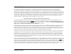
Product Overview Pictured below are the components included with a 110VAC Remote Power On/Off system. The items in the center picture represent a PP02 model. Note: A documentation CD-ROM may have been included instead of the printed manual. The items shown on the left are the additional items included with a PP03 model. The items shown on the right are the additional items included with a PPNT model. Beyond the additional items, the programming in the main unit also varies between each model.
Intelligent Power Module (IPM) - 110vAC model The Intelligent Power Module houses an electronic relay that will switch power to your computer, or any AC powered device, on and off. The module is activated (powered ON) via a signal from the Power On/Off +Aux control unit. Compare your module now to the illustration below and familiarize yourself with the terms that follow. If you have purchased the 220vAC version, refer to Appendix A - page 39 - for the overview and installation.
Power On/Off +Aux Control Unit The desktop portion of Remote Power On/Off is the Power On/Off +Aux control unit. This unit monitors the telephone line for RING, OFF-HOOK, and ON-HOOK conditions and signals the IPM to power the computer and peripherals on and off accordingly. TM ON/OFF STATUS ON/OFF Master Power Switch - this square momentary-contact switch is used to manually control the ON/OFF signal sent to the IPM, except when operating in the Reboot Mode.
LINE port - the incoming telephone line, from the wall-jack, connects to this RJ11 port. MODEM port - a telephone cable connects out from this RJ11 port to the modem's line-in port. . AUX port - a facsimile machine, answering machine, or other device sharing the same phone line connects to this RJ11 port. IPM PORT - the signal cable to the IPM connects to this RJ11/12 port.
A sample session, Power-ON Mode: 1 The user makes a modem call to the phone number of the line attached to the Power On/Off +Aux control unit. 2 The Power On/Off +Aux unit detects the incoming RINGs and counts them. After the first ring, the Power On/Off +Aux signals the IPM to power-ON the host PC and peripherals. 3 The line continues to ring as the PC is booting. A command in the PC's AUTOEXEC.BAT or Startup folder loads the host/communications software (i.e. pcANYWHERE, HyperAccess, etc.
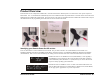
Installation This section covers the initial installation and testing of the Power On/Off +Aux control unit and the Intelligent Power Module (110vAC version). For additional installation information regarding the Windows 95/98/ME and Windows NT/2000/XP ShutDown/REBOOT versions refer to Appendix B and Appendix C respectively. For the 220VAC IPM, refer to page 39 of Appendix A. Default Settings Installation should be performed with the factory default DIP-switch configuration as shown below.
NOTE: UPS users must attach the wall-mount power supply to a second backed-up outlet provided on the back of the battery back-up. If not, a power outage will result in the PC powering off because the IPM will switch off if the Power On/Off +Aux unit looses power. Do not plug the power supply into an outlet that is switched on/off by the IPM. Insert the free end of the IPM signal cable into the port labeled "IPM PORT". The square "ON/OFF" switch should now control the IPM.
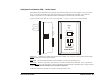
After installing Remote Power On/Off: PC STATUS IPM 0 OFF ON ON INTELLIGENT POWER MODULE TM OFF Telephone Wall Jack Power Supply ON OFF Power/Surge Strip Telephone Cables DIP SWITCHES LINE MODEM AUX IPM P ORT POWER MR TR SD RD OH CD AA HS Modem ON OFF To Modem Line-In Power Supply Power On/Off +Aux (back view) IPM Signal Cable Remote Power On/Off Installation • 14
Operating Modes and Options Remote Power On/Off offers three exclusive Operating Modes with several selectable options for each mode. Operating modes and options are determined by the Power On/Off +Aux control unit's DIP-switch settings. The two common Operating Modes are the Power-ON Mode (next page) and the REBOOT Mode (begins page 20). These operating modes, their individual options, and the DIP-switch settings, are discussed in the following sections.
Power-ON Mode The default operating mode for the Remote Power On/Off system is the Power-ON Mode. This mode allows a PC and peripherals to be turned-ON by an incoming telephone call and automatically turned-OFF after the call is completed. In this mode, the Power On/Off +Aux control unit monitors the telephone line for three conditions known generically as RING, OFFHOOK, and ON-HOOK.
Note: These Power-OFF Delay Time settings are useful to support post-connection operations, such as host software "Call-Back" services. The recommended selection for this option is two minutes. This will allow time for a re-dial in cases where the first connect fails (usually because the host PC takes too long to fully bootup), as well as plenty of time to re-connect if an accidental or unexpected disconnect occurs during a session.
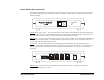
Power-OFF Delay Time DIP switches 3 and 4 are used to select the Power-OFF Delay Time value: 3|OFF 4|OFF 1 second Power-OFF Delay Time * 3|OFF 4|ON 2 minute Power-OFF Delay Time 3|ON 4|OFF 15 minute Power-OFF Delay Time 3|ON 4|ON 1 hour Power-OFF Delay Time DIP switch 5 determines when the Power-OFF Delay Time should apply: 5|OFF Power-OFF Delay Time only applies following hang-up, but only if the call had been answered (Offhook was detected). 5|ON Power-OFF Delay Time always applies.
Example DIP Switch Configurations, Power-ON Mode: Ring = Power-ON, Hang-up = Power-OFF 1 RING Power-ON 1 second Power-OFF delay ON 5 RING Power-ON 1 hour Power-OFF delay 1 2 3 4 5 6 7 8 1 RING Power-ON 2 minute Power-OFF delay ON ON 1 2 3 4 5 6 7 8 1 RING Power-ON 2 minute Power-OFF delay 15 RING Turn-OFF enabled ON 1 2 3 4 5 6 7 8 10 RING Power-ON 2 minute Power-OFF delay ON 1 2 3 4 5 6 7 8 10 RING Power-ON 15 minute Power-OFF delay ON 1 2 3 4 5 6 7 8 10 RING Power-ON 1 hour Power-OFF delay ON
REBOOT Mode The second operating mode is the REBOOT Mode. This mode is used to remotely reboot a device by temporarily interrupting its power source. The REBOOT Mode provides a full coldboot, practical for resetting remote network equipment, communications or fax servers, individual PCs, or any distributed device in a lock-up or error state. The REBOOT Mode is the reverse of the Power-ON Mode -- the power-ON signal to the IPM is constant to keep the devices powered on.
No Answer REBOOT With the No Answer REBOOT method, the Power On/Off +Aux control unit will count incoming RINGs and only initiate a reboot when a selected Ring-Count occurs and the call is not answered. If the call is answered (off-hook is detected) at anytime, either before or after the selected Ring-Count, the reboot is canceled. The minimum Ring-Count required to initiate a reboot can be set to either one (1) or eight (8).
This On-Hook REBOOT method does not require any changes to the host PC configuration (the modem can answer on any ring number desired). For example, the system will operate as follows (Ring-Count set to 8): A call placed to the host PC is answered, the modem connection is made, and the session is successful. When finished, the caller disconnects and a REBOOT occurs. A call placed to the host PC is answered, the modem connection is made, but the session is not successful. Hang-up to REBOOT.
Off-Hook (busy) REBOOT Option The one condition that can block you from initiating an immediate reboot with Remote Power On/Off is an endless busied-out line. If the Power On/Off +Aux unit is on the same line as the host modem, as is generally intended, and the modem refuses to hang-up, the line will remain constantly 'busy' and remote power control will be inaccessible.
Selecting the REBOOT Method DIP-switch 5 selects between the No Answer REBOOT and the On-Hook REBOOT methods: 5|OFF On-Hook REBOOT Method 5|ON No Answer REBOOT Method DIP-switches 5 and 7 select the +Aux Port (Secure) REBOOT method: 5|ON 7|ON Ring-Count Select DIP-switch 6 selects the minimum Ring-Count required to initiate a REBOOT when rings cease. 6|OFF Ring-Count required = Eight (8) 6|ON Ring-Count required = One (1) Off-Hook REBOOT Option DIP-switch 8 enables the maximum 2-hour Off-Hook limit.
Example DIP Switch Configurations, REBOOT Mode: Power is normally ON; REBOOT = Power-OFF, 30 second delay, Power-ON.
Infinite-On/Off Mode The Power-ON Mode allows a device to be turned on, remain on for the duration of the call, but always automatically turned back off up to 1 hour after the call is ended. On the other hand, the REBOOT Mode allows a device to be powered off, but only temporarily; power switches back on automatically after 30 seconds. Although both modes are ideal for a variety of remote communication needs, neither allows the IPM to simply be switched on (and stay on) or switched off (and stay off).
DIP Switch Configuration The following outlines the DIP switch positions for the Infinite-On/Off Mode. When the Infinite-On/Off option is enabled, the 15 Ring Turn-OFF and +Aux Feature must also be enabled. Power can then be switched ON by 1, 5, or 10 RINGs and switched OFF with 15 RINGs. In all cases, the unit must first be 'primed' as described earlier.
+Aux Feature The +Aux feature allows a single telephone line to be shared by a modem, the Power On/Off +Aux system, and one other telephone device, such as a facsimile machine or answering machine - which is attached to the AUX port.
Sharing a Single Phone Line The Power On/Off +Aux control unit, using relays, achieves line-sharing by controlling when the LINE port is continuous to the MODEM and AUX ports. With the +Aux Feature enabled, all normal or routine incoming calls are ignored (with respect to power control) and effectively routed to only the AUX device. To reach the MODEM and activate power control functions, a two-call method must be used.
Modem Priority Option The +Aux Feature has been designed to optionally allow priority to be given to the modem whenever the PC is fully booted and ready to answer calls. It allows you to choose whether or not the modem should be disguised when the system is already ON and fully booted. If the system is off, the two-call method must always be used because the modem will never be ready to answer (before the auxiliary device) until the PC is fully booted.
Sample Sessions The following sample sessions are common end-user configurations. They are provided as a guideline to better understand the possible Remote Power On/Off system configurations. Each sample is preceded by the appropriate DIP switch settings; a brief outline follows. ON 1 2 3 4 5 6 7 8 Power-ON Mode Power-ON Ring 1; 2 minute Power-OFF delay. Basic configuration for use with dedicated modem line.
ON 1 2 3 4 5 6 7 8 Power-ON Mode, +Aux feature Enabled Power-ON Ring 5; 2 minute Power-OFF delay. Popular configuration for secure power control and optional line-sharing between modem and one other device attached to the AUX port. 1 The user places a call to the phone number of the line attached to the Power On/Off +Aux. After one (1) ring is heard, the caller waits a couple of seconds then hangs-up. This first call will prime the Remote Power On/Off system.
ON 1 2 3 4 5 6 7 8 Power-ON Mode Power-ON Ring 1; 15 minute Power-OFF delay. Configuration for using the PC (with fax/modem) as a facsimile machine. Requires dedicated phone line for fax server's fax-modem. 1 An associate, wishing to send you a fax, enters the telephone number for your fax/modem and instructs the sending fax machine to dispatch the fax. The machine dials the number. 2 The Power On/Off +Aux unit detects the incoming RINGs.
ON 1 2 3 4 5 6 7 8 REBOOT Mode, Power is normally ON No Answer REBOOT Method; minimum rings required to effect a reboot = 1 2-hour Off-Hook (busy) REBOOT - Enabled Popular REBOOT configuration for BBS (bulletin board server), dial-up email or access servers, or high-traffic automated systems. Any incoming call that is not answered will initiate a reboot. Modem lock-ups that cause a busiedout line will be cleared automatically after 2 hours.
ON 1 2 3 4 5 6 7 8 Infinite-On/Off Mode 1 Ring/Hang-up to 'prime', wait 10 seconds then place second call: 5 RINGs to Power-ON, or 15 RINGs to Power-OFF This configuration is for users who prefer the Remote Power On/Off to behave like a real switch -- to power-ON and stay on, or power-OFF and stay off. In this mode, line-sharing is not possible; only a single phone device (i.e. modem) can be attached to the AUX port - the MODEM port will be empty.
Appendix A ON/OFF and STATUS LED Activity The front panel of the Power On/Off +Aux control unit contains two indicator lights. These LEDs inform the user of the current power status, present phone-line condition, and indicate whether or not the power has been activated remotely since it was last turned off manually. The activity of both lights varies according to the Operating Mode you have chosen.
• ON ~ The power is ON and the REBOOT function is disabled. Incoming calls cannot initiate a remote reboot. LED is ON. • OFF ~ A REBOOT is in progress. The power is currently OFF as part of the off>delay>on reboot cycle. Power will turn back on within 30 seconds. The LED is solid OFF.
Power-ON and Infinite-On/Off Modes In the Power-ON and Infinite-On/Off operating modes, the idle (ON-HOOK) state of the STATUS LED will indicate whether or not the power has been turned on remotely since the last time it was powered off manually. Only two distinct flash rates will occur: either a mostly off slow flash, or a mostly on slow flash. With just a glance you will instantly know if a phone call had activated your PC since the last time you powered it off.
220 VAC Intelligent Power Module Overview/Installation 0 INTELLIGENT TM POWER MODULE STATUS For users that have purchased the 220VAC version of Remote Power On/Off, the Intelligent Power Module is a universal design utilizing common IEC 320 connectors. Functionally, the IPM will operate the same as described earlier in the 110V IPM section, but will require modification of a multiple outlet/surge strip specific to your country and its outlet type.
Step 2 Locate the included cable-mount IEC 320 /C14 male inlet connector assembly (illustrated below) and a multiple outlet power or surge-protection strip specific to your country of installation (not included). The next action requires the user to install the IEC 320 /C14connector assembly to the end of the country specific multiple outlet strip (replacing the country specific male plug).
C Loosen each screw on the three terminals, then attach the appropriate conductor to each, and tighten the screws. Be sure to attach each conductor to the appropriate terminal, as shown in the above diagram. Also note that the inside of the IEC320 male assembly identifies each terminal with an "N" for Neutral, "L" for Line, and a " " symbol for Ground (in the middle).
Appendix B - Windows 95/98/ME ShutDown Introduction Windows 95, Windows 98, and Windows Millennium Edition must be shut down prior to turning off power. When a user is at the computer, the user can perform the necessary shutdown by selecting Shut Down from the Start menu on the task bar. With Remote Power On/Off, the user is not at the computer, and consequently may not be able to perform the necessary shutdown prior to the power being turned off.
The following diagram shows a complete installation with the Y-cable and ShutDown adapters. This diagram replaces the "After installing Remote Power On/Off" diagram on page 14.
Functional Changes to the Remote Power On/Off Due to the modified firmware in the Power On/Off +Aux ShutDown/REBOOT control unit, there are some minor functional variations from those described earlier in this guide. All changes are related to the addition of the shutdown function. Minimum ON Time: The Minimum ON Time, described earlier on page 15, has been increased from one (1) minute to 90 seconds.
Starting with the power OFF and the LED off, pressing the button once will turn power ON and the LED will go on green. Pressing the button a second time will signal a shutdown to the Windows 95/98/ME system and the LED will start to blink, indicating a shutdown has been started. After one (1) minute, the shutdown will be complete, and power will turn OFF automatically.
The first time AutoShutDown runs, it will prompt you to choose the port to which the ShutDown adapter is attached and to enable it. Once you have done this, you should minimize AutoShutDown and go on with your work. AutoShutDown will continue to monitor the shutdown port while you run other applications. IMPORTANT: AutoShutDown can initiate a Windows 95/98/ME shutdown in one of two ways, either forced or normal.
Appendix C - Windows NT/2000/XP ShutDown Introduction Windows NT, Windows 2000 and Windows XP must be shut down prior to turning off power. When a user is at the computer, the user can perform the necessary shutdown manually. With Remote Power On/Off, the user is not at the computer, and consequently may not be able to perform the necessary shutdown prior to the power being turned off. To solve this problem, Server Technology introduced the Power On/Off +Aux SHUTDOWN/REBOOT for Windows NT, model #PPNT.
The following diagram shows a complete installation with the Y-cable and ShutDown adapter. This diagram replaces the "After installing Remote Power On/Off" diagram on page 14.
Functional Changes to the Remote Power On/Off Due to the modified firmware in the Power On/Off +Aux ShutDown/REBOOT unit, there are some minor functional variations from those described earlier in this guide. All changes are related to the addition of the shutdown function. Minimum ON Time: The Minimum ON Time, described on page 15, has been increased from 1 to 5 minutes.
Starting with the power OFF and the LED off, pressing the button once will turn power ON and the LED will go on green. Pressing the button a second time will signal a ShutDown to the Windows NT/2000/XP system and the LED will start to blink, indicating a ShutDown has been started. After 3 minutes and 30 seconds, the ShutDown will be complete, and power will turn off automatically.
Remote Power On/Off for Windows NT, model #PPNT, makes use of the UPS Service much the same way as a UPS does. Whenever Remote Power On/Off is going to power the system OFF, it signals the UPS Service to ShutDown the operating system before doing so. The Remote Power On/Off, however, does not act entirely like a UPS. Both the Power Failure and Low Battery signals occur at the same time and the amount of time before the power is turned OFF is fixed at 3 minutes 30 seconds.
2) Choose the options as illustrated below, then click OK: 3) To configure the UPS Service for the proper COM port and operating parameters of the Remote Power On/Off, select "UPS" from the Control Panel. The UPS window will be displayed: Selected the appropriate COM port and choose the other options as shown above, then click OK.
Windows 2000/XP UPS Service Configuration Windows 2000 and Windows XP, similar to Windows NT, includes a service for an Uninterruptible Power Supply (UPS). The mechanism for notifying Windows 2000/XP to shut down is nearly the same as for NT. The only difference between Windows NT and Windows 2000/XP is the software used to monitor the serial port for the ShutDown notification from the Power On/Off +Aux.
The Power Options Properties screen will appear. Click the UPS tab. The Power Options Properties screen will appear similar to the screen capture down below (on the left). 2) Press the ‘Select...’ button to proceed to the UPS Selection screen (shown below, right) 3) On the UPS Selection screen specify "Generic" as the manufacturer type. Next, click on “Custom” in the ‘Select model:’ field, then proceed to choose the appropriate COM port.
4) On the UPS Interface Configuration screen (shown below, left), enable the UPS Signal Polarity options as illustrated. Click ‘Finish’ to return to the Power Options Properties screen (see screen on previous page, left). Press the ‘Configure...’ button on the Power Options Properties screen to proceed to the UPS Configuration screen (shown below, right). 5) On the UPS Configuration screen (above right), configure the options as shown.
Operational Behavior, Windows 2000/XP ShutDown Configured as shown in the previous screen shots, and after a call initiates a power-OFF or a REBOOT, the Remote Power On/Off and the Windows 2000/XP UPS Service will work together in the following sequence: Time 0 5 sec. 35 sec. 65 sec. 95 sec. 120 sec. 121 to 209 sec. 210 sec. Event Power failure signaled by Remote Power On/Off First warning message that a power failure has occurred Second warning message that a power failure has occurred.
To test the UPS Service, insert the loopback plug into the RJ11 end of ShutDown adapter. Within 15 seconds of insertion, the first warning message from the Windows NT/2000/XP UPS Service should appear. The shut down has been initiated.
Windows NT/2000/XP Automatic Logon When a Windows NT system boots, the operating system expects a local user to press the key sequence to bring up the logon dialog box from which the user will login with their user name and password. This poses a problem for remote booting since a user is not at the system to press the expected key sequence. Similarly, Windows 2000 and Windows XP may require a user be present to provide manual login information as well.
Appendix D - Upgrade Kits Server Technology offers three distinct versions of Remote Power On/Off +Aux: 1) Model #PP02, a non-shutdown version ideal for use with systems or devices that do not require an orderly shut down; 2) Model #PP03, a ShutDownequipped version capable of attempting an orderly shut down of Microsoft's Windows 95/95/ME; 3) Model #PPNT, a ShutDown-equipped version capable of attempting an orderly shut down of Microsoft's Windows NT/2000/XP.
Is Your Power On/Off Control Unit Upgrade-Compatible? Only "+Aux" versions of Remote Power On/Off are capable of being upgraded. "+Aux" versions are easily identified by the writing on the front bezel of the Power On/Off control unit. Your unit must have either "Power On/Off +Aux" or "POWER ON/OFF +Aux SHUTDOWN/REBOOT" printed on its face. All "+Aux" versions are ultimately compatible with any of the three upgrade kits.
• Check position U2 on your unit. This is the location of the ROM chip. Is the ROM chip in a socket (removable), or is the ROM chip soldered directly to the circuit board (not removable)? • Check position R14 on your unit. Does R14 contain a resistor, similar to the following picture? NOTE: Color of resistor and stripes may vary. If the ROM is in a socket and R14 does not contain a resistor, then your unit is fully compatible with any available Upgrade Kit.
4) Identify the correct direction to insert the new Upgrade ROM into the socket. Look at the socket on the circuit board. Make note that one end of the socket is notched, the end closest to the side of the unit. One end of the new ROM is also notched. To install the ROM correctly, be sure that the notch on the socket and the notch on the ROM are aligned on the same side. Refer to the picture two-pages back, and the following illustration to help identify the proper alignment.
FCC Compliance Information Notification To The Telephone Company This equipment complies with Part 68 of the FCC Rules. The REN is useful to determine the quantity of devices you may connect to your telephone line and still have all of those devices ring when your telephone number is called. In most, but not all areas, the sum of the RENs of all devices connected to one line should not exceed five (5.0).
Specifications Power On/Off +Aux Control Unit Interface Specifications Line, Modem, Aux and IPM Ports: 6 wire modular RJ11C Telephone Ringer Equivalence: 0.4A Power Input - 9vDC, 300mA, Polarity: center-negative The product utilizes the standard telephone company RING signal on tip/ring phone lines. It can operate with 30V RMS minimum ring signal with 33% minimum ring time in 6.5 second maximum ring cycle.
Warranty & Support Warranty and Limitation of Liability Server Technology, Inc. agrees to repair (parts & labor) or replace Products that fail due to a defect within twelve (12) months after the shipment date of each Product unit to Buyer ("Warranty Period"). For purposes of this Agreement the term "defect" shall mean the Product fails to operate or fails to conform to its applicable specifications. Any claim made pursuant to this Agreement shall be asserted or made in writing only by Buyer.
Product Registration Registration is your key to special offers and services reserved for Registered Users. • Excellent Technical Support Services • Special Update and Upgrade Programs • Warranty Protection • Extended Warranty Service Options • New Product Information Register your products on-line today!: www.servertech.com/support/supportindex.htm Technical Support We understand that most everyone has questions when using a new product.
Return Merchandise Authorization If you have a unit that appears to not be functioning properly and are in need of technical assistance or repair services: Submit a request for support by phone at the number on the previous page, or via the web at www.servertech.com/forms/techrequest.