
Troubleshooting guide

13
Installation and Service Manual
INSTALLATION
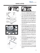
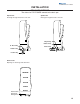
RECIRCULATION LINES AND PUMP
1A
1C
1D
1B
1F
1G
1E
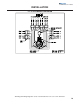
FIGURE 1
1. If required secure recirculation pump (1A) to counter
or under counter that unit is installed on (See Figure
1). Run insulated beverage line (1B) from the barded
pump outlet fitting up to the right barbed cooling coil
inlet (2A) on back of dispenser and secure both ends
of line to the barbed fittings with otiker clamps (See
Figures 1 and 2). Connect another insulated bever-
age line to left barbed cooling coil outlet (2B) on back
of dispenser and secure line to barbed fitting with otiker
clamp (See Figure 2).
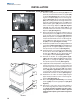
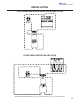
2. Wrap cork tape insulation around the barbed inlets
(3A) and insulated beverage lines (3B) as shown (See
Figure 3
). Installation of cork tape must be done
properly to prevent condensation and tempera-
ture gain of circulating water.
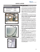
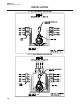
3. Route insulated beverage line from the cooling coil
outlet (2B) up through either the back or bottom of
tower (4A) as shown (See Figures 2 and 4). Route
insulated beverage line through left side hole in the
valve mount plate (4B) as shown (See Figure 4).
Connect insulated beverage line to left side of barb
fitting (4C) and secure line to barbed fitting with otiker
clamp (See Figure 4). Connect the last insulated
beverage line to right side of barbed fitting (4E) and
secure line to barbed fitting with otiker clamp (See
Figure 4). Wrap fitting and insulated beverage lines
(4D) with cork tape insulation (See Figure 4).
Instal-
lation of cork tape must be done properly to pre-
vent condensation and temperature gain of
cir-
culating water
.
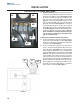
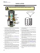
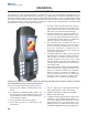
4. Chiller Installations: When using a refrigerated
chiller (5A) for cooling plain water supplied to tower
the recirculation pump can be mounted to the exte-
rior cabinet of chiller (See Figure 5)..
5. Chiller Installations: Attach insulated beverage line
(1B) to the pump outlet fitting and secure with otiker
clamp. Then run insulated line (1B) to the plain water
coil inlet (5B) of the chiller (5A). Secure line to the coil
inlet (5B) of the chiller (5A) mechanically. If applicable
us an otiker clamp (See Figures 1 and 5).
6. Chiller Installations: Connect another insulated bev-
erage line to the plain water coil outlet (5C) of the
chiller (5A). Secure line to the coil outlet (5C) of the
chiller (5A) mechanically. If applicable us an otiker
clamp (See Figure 5).
FIGURE 2
FIGURE 3
2A
2B
3A
3B
PARTS INCLUDED IN KIT NO: 020000783
Qty. Description Part Number
1 Recirculation pump/w/fittings 020000780
3 Line insulated beverage 020000781
1 Instructions Recirculation lines 020000782
10 Clamp Otiker 15.7 15.7-706R
6ft Tape Cork Insulation RM051120