
Troubleshooting guide

12
Installation and Service Manual
INSTALLATION
PRECHILL COIL RETROFIT KIT
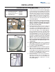
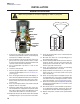
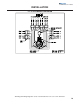
7. Place the cooling coil heat exchanger (5A) into the
previously cleared and cleaned ice storage bin (5B)
as shown (See Figure 4). Be sure the coil is rest-
ing flat on coldplate (5C) of the ice beverage dis-
penser (See Figure 5). The inlet and outlet fittings
(8E) of the cooling coil heat exchanger will exit over
previously trimmed 3.00 inch open area (4C) of the
rubberized bin gasket (4A) in the back left corner
of the ice beverage dispenser (4B) (See Figures
3 and 6). The inlet and outlet fittings (8E) of coil
should be visible from the back of the ice beverage
dispenser (8C) (See Figure 6).
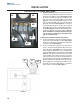
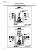
8. Remove protective covering from adhesive tape on
back of the plastic cover (6A) that is factory installed
on the cooling coil heat exchanger (6B) (See Fig-
ure 6). Place plastic cover (6A) snuggly into previ-
ously cleaned left inside corner of ice beverage dis-
penser (8C) flush with the top of the ice storage
bin (8D) as shown (See Figures 4 and 6).
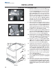
9. Reinstall the paddle wheel area (3G), paddlewheel
area bushing [where applicable] and paddlewheel
(3F) in the ice storage bin (3A) that components
were previously removed from (See Figure 2).
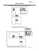
10. Install the plastic cover support bracket (7A) under
the left side of the bin liner (7B) when reinstalling
the bin liner (7B) and the four knurled bin liner
screws (3E) as shown (See Figures 2 and 5).
11. Reinstall the double –D coupling [where appli-
cable], agitator bar (7C) and paddlewheel pin or pins
(7D) in the ice storage bin (7E) that components
were previously removed from (See Figure 5).
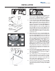
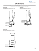
12. If applicable reinstall strip lid kit or components pre-
viously removed for access to install cooling coil
heat exchanger in the ice beverage dispenser. The
original left side strip lid panel (2A) and support
brace
(2B) [where applicable] will be replaced by
a new left side strip lid panel and support brace
included with some but not all kits (See Figure 1).
13. Reinstall the ice maker or makers (1A) using the
proper install procedures on the ice beverage dis-
penser (1B) (See Figure 1).
14. Place label (8A) [Part No.5011948] near existing
serial tag (8B) of ice beverage dispenser (8C) (See
Figure 6).
15. Reconnect or turn on the water, power supplies to
the ice beverage dispenser and ice maker or mak-
ers. Check for leaks and make sure the ice bev-
erage dispenser, ice maker or makers operate
normally before placing units back into general
service.
8A
8B
8C
8D
8E
FIGURE 6
FIGURE 5
FIGURE 4
6A
5A 5C
5B
7A
7B
7C
7D
7E