
Specifications

8
2.3. High Voltage Electrical
Connections
The installing contractor must ensure
that all electrical wiring satisfies all
National, State and Local codes.
2.3.1 Wire and Fuse Sizing
The field-installed power supply wires and
over current devices must be sized to
handle the minimum ampacity of the
dehumidifier without exceeding the
maximum fuse size rating. Both the MCA
and MOP are indicated on the unit
nameplate.
Improper wiring to the dehumidifier
could create the possibility of
shock and may lead to system
failure.
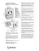
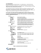
2.3.2 Line Voltage Connections
Figure 7 shows typical power wiring
connections. Single-phase units power
supply must have 3 wires (2 power, 1
ground). On three phase units the power
supply must have 4 wires (3 power, 1
ground). Connect the power supply wires
to the main power block located inside the
electrical panel.
Always check the nameplate voltage before
connecting to the unit.
Figure 7 – Power Wire Connection
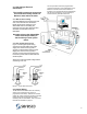
2.4. Control Wiring
The NE Series dehumidifiers have all necessary
sensors unit mounted and set points pre-
programmed at the factory. Remote duct heaters,
outdoor air-cooled condensers, auxiliary pool water
heaters and remote exhaust fans all require
interfacing with the dehumidifier. Their connection
terminals are identified on page 33
The microprocessor has been programmed to
control their operation. Figure 8 illustrates how an
Ethernet connection to the Internet allows all
functions to be monitored by trained professionals
with Seresco’s Websentry. It is the final step to
ensure the facility operates trouble free.
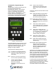
Figure 8 – Control Wiring