
Specifications

3
TABLE OF CONTENTS
1. Introduction ...................................................................………………...................…… 4
1.1 Packaged Mechanical Refrigeration Systems............................................….........…… 5
1.2 NE Series Dehumidifier features……..............................................….........…………… 6
2. Installation .................................................................................………….……………..
7
2.1 Uncrating and Inspecting..................................................................................….…… 7
2.2 Mounting and Service Clearance………………………….........................................…… 7
2.3. High Voltage Electrical Connections ...................................................................…….. 8
2.3.1 Wire and Fuse Sizing.............................................................................…… 8
2.3.2 Line Voltage Connections.................................................................….…… 8
2.4. Control Wiring......……………………...................................................................……… 8
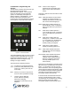
2.5. Controller and Programming....................……........................................................…… 9
2.5.1 Normal Mode and Programming……………........................................…….. 10
2.5.3 Logs…………….....................................……………………………………….. 11
2.5.5 Sensors and locations………….....................................…………………….. 12
2.6. System Design Overview….................................................................…………....……. 13
2.6.1 System duct design and air pattern ………...................................….......….. 13
2.6.2 Evaporation rate and latent loads…………...................................….......….. 14
2.6.3 Required Access Space……………………...................................….......…… 14
2.6.4 Exhaust Air……….........…………………………….........................…......…… 15
2.6.5 Supply Air flow…………………………….…...................................…......…… 15
2.6.6 Cooling and Heating loads…………………....................................…......…… 15
2.6.7 Outdoor Air……………………………………...................................…......…... 15
2.7. Condensate Drain ….........................................................………............................…… 16
2.8. Pool Water Heating (PH AND PV Models Only)…..................................……………….. 16
2.8.1 Water Flow Schedule …………................................................................…... 16
2.8.1 Pool Water Piping Diagram ………...............................................…………… 17
2.9. Outdoor Air-cooled Condenser Installation......................…………...........................….. 18
2.9.1 Refrigerant Piping to Remote Condensers....……................................….. 18
2.9.2 Charging of Remote Condensers…......................………………………....….. 19
3. Pool Water Chemistry ….................……………………..…...............……….............… 20
4. Start-up Procedures …...........................…………….....................………….........…….. 21
4.1. Pre Start-up …........................................................…………….................................….. 21
4.2. Start-up Procedure ….............................................………........................................….. 21
4.3. System Operation Modes…..................................................................................……... 22
4.3.1 Power On………………………….….........................................................…... 22
4.3.2 Dehumidification Mode…......................……………...................................…. 22
4.3.3 Air Conditioning Mode …....................................................……………….….. 22
4.3.4 Pool Water Heating Mode (PH AND PV Models Only)…...........…………….. 22
4.3.5 Blower Operation….................................................………........................…. 22
4.3.6 Compressor Start Sequence…..........................................................….....…. 23
4.3.7 Air Heat Demand ….........................................................................….......…. 23
5. Service and Maintenance…................................................………………….……....... 23
5.1. Routine Maintenance….........................................................................………….......…. 23
5.2. Compressor Replacement…..................................................................................……. 23
6. Service References …………………………………………………………………………. 24
6.1. Nameplate …....................................................…………………................................…. 24
6.2. Mechanical System Trouble shooting….....................................................................…. 25
6.3. Microprocessor Trouble shooting…...........................................................................…. 27
6.4. Blower Adjustment Procedure…...................................................…………..............…. 28
6.5. Basic Unit Operation …...........................................................……………….……....…. 28
6.6. Factory Start-up Supervision…..…..........………….................................................…… 29
6.7. Warranty…………………….…..................................................…............................…… 30
6.8. Refrigeration Diagrams……………………….…....…..............….………………………… 32
6.9. Field Wiring Diagram…………………….…....…................….………………………… 33
6.10. Typical Electrical Panel Layout………..……………………..…......…..............…… 33
6.11. Warranty Registration and Start-up Report……………………..…......…..............…… 34