
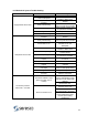
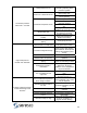
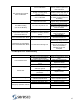
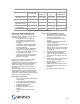
Specifications

23
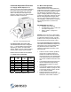
4.3.6 Compressor Start Sequence
All NE units have a pump down sequence
and anti-short cycle timer. When a demand
requires the compressor to operate the
following sequence occurs:
Blower operation confirmed by
microprocessor and ASCT sequence
completed.
Pump down solenoid opens.
50 psig will close the low pressure
safety switch contact.
Compressor starts.
4.3.7 Space Heat Demand (Unit Mounted
or remote)
The Seresco unit’s microprocessor is
designed to control a space-heating coil
(unit mounted or remote). When the room
temperature drops below the set point the
microprocessor will send a signal to the
heating coil’s control mechanism.
5. Service and Maintenance
The NE unit is a piece of mechanical
equipment, which requires routine
maintenance and service. The service
required is nothing more than a traditional
commercial air conditioner. If a problem is
encountered, refer to the T
ROUBLESHOOTING
GUIDE in Section 6.2.
If all suggestions in the “Trouble shooting
guide” have been exhausted, call Seresco’s
service department. Be sure to have the
Model and Serial number when you call.
1-888-SERESCO (737-3726)
If the unit has been ordered with the internet
connection capabilities, Seresco or the local
factory representative can directly access
the unit and diagnose the problem from their
facility.
5.1. Routine Maintenance
Seresco dehumidifiers are designed for
years of reliable service. In order to ensure
this, they require periodic maintenance.
5.1.1 Monthly Service
Check the air filters and replace them if
necessary.
Check all water connections for leaks
and ensure all hose clamps are tight.
5.1.2 Annual Service
Tighten all field and factory electrical
connections.
Verify that the coils in the dehumidifier
and the remote outdoor air-cooled.
condenser or dry cooler are clean. Use
compressed air or a commercial coil
cleanser if they are dirty.
Verify that the airflow around the remote
condenser or dry cooler remains
unobstructed.
Check drainpan and clean out any
residue that may have accumulated.
Conduct a complete system check up.
This requires the service technician to
fill out page #2 of the Warranty
Registration and Start-up Report. A
copy of this worksheet is located on
page 34. This form is a valuable
maintenance tool, which can help to
uncover problems before they get
expensive.
5.2 Compressor Replacement
Compressor failures can be caused by:
liquid slugging, air or moisture in the
refrigerant circuit, solid contaminants,
excessive heat or electrical service
malfunctions. To avoid repeated failures, the
cause of the failure must be determined and
then corrected. If the compressor has failed
because its’ motor has burned out, the
refrigerant, oil, and piping is contaminated.
The procedure in section 5.2.1 should be
followed to replace the compressor and
clean the refrigerant system.
All acid must be removed from the
system to avoid future burnouts.
Use an oil test kit to determine the severity
of the burnout. Be sure to follow directions
provided by the test kit manufacturer for
complete system cleansing and acid
removal. Make sure you use rubber gloves
and eye protection, as contaminated
refrigerant and oil can cause severe burns!
5.2.1 Compressor Burnouts
If the compressor has failed due to a
burnout, the entire refrigerant charge has
been contaminated. In the service mode, all
solenoid valves can be opened in order to
evacuate the circuit completely. On systems
equipped with an optional pool water
condenser, take care to avoid freezing the
condenser during evacuation.