
Specifications

16
dry portion of the deck will not factor into the IAQ
issues.
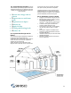
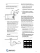
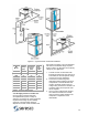
The NE Series units have an outdoor air opening
with a filter and manual balancing damper.
Optional unit mounted motorized dampers and
time clocks are available. Figure 17 illustrates a
typical connection configuration.
Figure 17 – Outdoor Air Duct Detail
Outdoor air requires considerable heating in
the winter and can add significant moisture
in the summer. Exceeding code
requirements is not recommended as it will
increase the operating expenses and may
increase the size of the dehumidifier.
Locate the outdoor air intake away from any
sources of airborne contamination such as
exhaust fans or plumbing vents.
If more than 20% of the total airflow is
outdoor air or if the winter design
temperature is below 10ºF: The outdoor air
must be preheated to 65ºF.
If outdoor air is introduced into the return
duct: it must be preheated to the space
temperature.
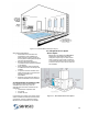
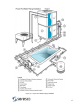
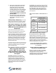
2.7. Condensate Drain. The dehumidifier is
a draw through configuration as a result the
Figure 18 – P Trap
entire cabinet is under negative pressure.
Without a trap, condensate will not drain and the
unit will overflow into your mechanical room.
Per Figure 18 pitch the condensate drain line
a minimum of 1/8” per linear foot, and
support the pipe with code-approved
hangers at least every 5 feet.
If the drain line passes through an
unconditioned space, heat tracing is required
to prevent the condensate in the drain from
freezing.
When gravity disposal is not possible, a
condensate pump can be used. Follow the
pump manufacturer’s installation
instructions.
2.8. Pool Water Heating (PH and PV
Models Only).
The energy a pool loses
through evaporation represents approximately
90% of its annual water-heating requirement. The
Seresco unit captures 100% of this heat as a by-
product of the dehumidification process and can
return this energy back to the pool, thereby
greatly reducing pool water heating costs. During
the cooling season the dehumidifier is capable of
providing 100% of the pool’s water-heating
requirement. Refer to Figure 18 for proper pool
water piping connections to the NE Series unit.
2.8.1 Water Piping Connections.
The NE
unit requires only a fraction of the total water
being circulated by the main filter system. Refer
to Table 4 or the unit nameplate for nominal
water flow rates.
The water circuit should tap off the main pool
water line downstream of the main filter and
upstream of the auxiliary pool water heater
and chemical feeder.
Install an auxiliary water pump to deliver the
unit’s required water flow. It is an open
system and the pool’s main circulating pump
can rarely accommodate additional system
pressure.
All systems require auxiliary pool water
heaters. The Seresco unit will control
their operation when it is not able to
provide water heating.
Max Water Flow Rates (GPM) &
Pressure Drop (PSI)
Model GPM PSI
004
6 6
005
8 4
006
12 5
007
12 6
008
16 4
010
18 6
012
22 6
014
25 6
Table 4. Unit GPM Schedule