
Specifications

12
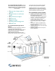
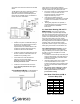
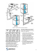
2.5.5 Sensors and location.
Figures 11 & 12 identify where the sensors are
located in the NE Series units. Each sensor is
accessible through the Command Center or Web
Sentry. Sensor history is stored and can be
reviewed in tabular form.
All Sensors can be calibrated in service mode.
Figure 11 – Sensor location in a Vertical unit
Sensors:
Room air temperature
Room air humidity
Pool water entering temperature
Pool water leaving temperature
Outside air temperature
Air temperature leaving the evaporator
Supply air temperature
Compressor hot gas discharge temperature
Compressor suction gas temperature
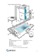
Refrigerant Pressure Transducers:
Refrigerant High pressure
Refrigerant Suction pressure
These allow the user or serviceman to access the
vital refrigerant pressures through the operator
panel of the microprocessor rather than having to
connect a set of refrigerant manifold gauges.
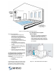
Figure 12 – Sensor location in a Horizontal unit