
Owner Manual


2) Installing Wall Panels and Post Bracket: (Make sure speed on drill is adjusted to #7)
*If you purchased Shower Valve Trim Set with removable wall panel, See 2 j for instructions to install
the removable panel.*
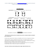
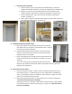
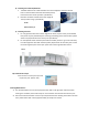
a. On the face of the post where the wall/header will sit, place the post bracket jig on top of post.
(See PIC 2a) *Important: This will keep header and top of the wall panel aligned.*
b. Place bracket inside jig. Attach the bracket using the self-tapping ¾” stainless steel screw
(provided in wall panel box). (See PIC 2b)
c. Measure down from the TOP of the post bracket 72 1/2” and make a mark. Above that line
measure in 1” from the side of the post and make another mark forming an upside down “T”.
(See PIC 2c)
d. Align the bottom of the post bracket with the bottom line of the upside down “T” and center the
post bracket screw hole with the center of the upside down “T”. Attach the bracket using the
self-tapping ¾” stainless steel screw (provided in wall panel box). (See PIC 2d)
e. Repeat steps 2a thru 2d on adjacent post where wall panel will be installed.
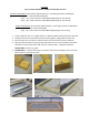
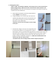
f. Set the wall panel into the bottom brackets first, and then pull the posts away at the top. The top
of the wall panel should clear the top wall bracket and fit snug. If the wall panel does not clear
the top panel bracket and fit snug loosen the post bolts. (See PIC 2f)
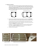
g. Fasten the wall panel to the brackets using the self-tapping ¾” stainless steel screws on all four
corners of the wall panel. *All screws must be facing the interior of the shower & centered on
bracket. (See PIC 2g)
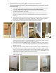
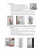
h. Continue this process until all wall panels are installed. If there is any part of the shower facing
an existing structure, and a wall panel is not being installed, a header will be provided in order
for you to secure the two posts. This header will also need to be installed on the top of the door.
Follow steps 2a and 2b to attach the brackets, and then attach the header (OPEN SIDE UP) to the
brackets using self-tapping ¾” stainless steel screws. (See PIC 2h)
i. Tighten the bottom bolts of each post to secure the unit. The post must be tightened evenly to
ensure unit will be level.
PIC 2f
PIC 2g
PIC 2h
PIC 2b
PIC 2c
PIC 2d
PIC 2a
PIC 2g
PIC 2h