
Integration Guide
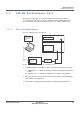

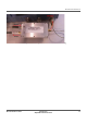
Table Of Contents
- Module Integration Guide
- Preface
- About this Guide
- Introduction
- Manufacturing Process
- Hardware Integration Recommendations
- PCB Layout Rules
- Bring-Up and Testing
- Hardware Test Preparation
- Abbreviations

RF INTERFACES PREPARATION
38 PROPRIETARY MODULE INTEGRATION GUIDE
SEQUANS Communications
Figure A-1: Shield Box Cavity View
Figure A-2 shows the required configuration for calibration and screening. It
consists of:
• 1 x ZN2PD2-50-S + power splitter if the signal analyzer and the signal
generator are two distinct equipments. R&S® CMW500 for instance allows
the use of a single bidirectional RF port and prevents the need of a power
splitter.
• 1 x RF cable to the MXA (if needed)
• 1 x RF cable to the MXG (if needed)
• 1 x RF cable to the DUT (in the shield box)