
Integration Guide
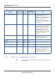
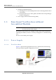
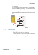
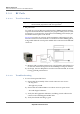
Table Of Contents
- Module Integration Guide
- Preface
- About this Guide
- Introduction
- Manufacturing Process
- Hardware Integration Recommendations
- PCB Layout Rules
- Bring-Up and Testing
- Hardware Test Preparation
- Abbreviations

BRING-UP AND TESTING
FUNCTIONAL VERIFICATION WITHOUT ASSEMBLED MODULE
MODULE INTEGRATION GUIDE PROPRIETARY 29
SEQUANS Communications
• Test voltage values
Test the DC nature of the voltage with an oscilloscope before connecting
the DUT. Once the DC source is confirmed, you can power the DUT and
measure accurately the test points voltage with a multimeter. At this stage,
only VBAT1 can be tested.
Check at each voltage test point, as illustrated on Figure 5-2, that the
voltage value corresponds to what is expected. The values must be in the
range specified in the VZM20Q Datasheet, section Electrical Operating Condi-
tions.
Figure 5-2: Measuring Voltage Value (VZM20Q)
5.3.1.2 Troubleshooting
• One power supply is incorrect
– If the voltage is zero for one or more supply outputs
- Check any resistor link to detect unexpected shunts or open circuits.
– If the voltage is incorrect for one of more supply outputs
- Check any resistor link to detect unexpected shunts or open circuits.
dW
ϭsϴ
sDϮϬY
ϬZ
ϬZ
ϬZ
sϭͺW
sϮͺW
sdϭ
sd
dW
dW
dW
'E
ϬZ
ϯsϬ