
Integration Guide
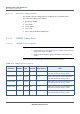
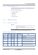
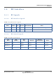
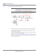
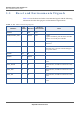
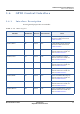
Table Of Contents
- Module Integration Guide
- Preface
- About this Guide
- Introduction
- Manufacturing Process
- Hardware Integration Recommendations
- PCB Layout Rules
- Bring-Up and Testing
- Hardware Test Preparation
- Abbreviations

HARDWARE INTEGRATION RECOMMENDATIONS
GPIO CONTROL INTERFACE
MODULE INTEGRATION GUIDE PROPRIETARY 21
SEQUANS Communications
3.6 GPIO Control Interface
3.6.1 Interface Description
Several general purpose IOs are available:
Table 3-11: GPIOs Signals
Pin Name Pin Number Direction
Electrical
Characteristics
Notes
GPIO14/TXD1 78 In/Out 1V8 UART1 TXD (Input) alternate
function to GPIO. See Section
UART1 Interface.
GPIO15/RXD1 80 In/Out 1V8 UART1 RXD (Output) alternate
function to GPIO. See Section
UART1 Interface.
GPIO17/CTS1 81 In/Out 1V8 Optional UART1 CTS (Output)
alternate function to GPIO. See
Section UART1 Interface.
GPIO38/CLK1 82 In/Out 1V8 Optional UART1 CLK (I/O)
alternate function to GPIO. See
Section UART1 Interface.
GPIO16/RTS1 83 In/Out 1V8 Optional UART1 RTS (Input)
alternate function to GPIO. See
Section UART1 Interface.
GPIO41/DTR0 84 In/Out 1V8 Optional UART0 DTR (Input)
alternate function to GPIO. See
Section UART0 Interface.
GPIO39/DSR0 85 In/Out 1V8 Optional UART0 DSR (Output)
alternate function to GPIO. See
Section UART0 Interface.
GPIO24/DCD0 88 In/Out 1V8 Optional UART0 DCD (Output)
alternate function to GPIO. See
Section UART0 Interface.
GPIO25/RING0 89 In/Out 1V8 Optional UART0 RING (Output)
alternate function to GPIO. See
Section UART0 Interface.