
Integration Guide
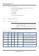
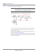
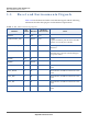
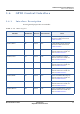
Table Of Contents
- Module Integration Guide
- Preface
- About this Guide
- Introduction
- Manufacturing Process
- Hardware Integration Recommendations
- PCB Layout Rules
- Bring-Up and Testing
- Hardware Test Preparation
- Abbreviations

HARDWARE INTEGRATION RECOMMENDATIONS
RESET AND ENVIRONMENTAL SIGNALS
20 PROPRIETARY MODULE INTEGRATION GUIDE
SEQUANS Communications
3.5 Reset and Environmental Signals
Table 3-10 lists the Reset and other environmental signals and the following
subsections describe their purpose and termination requirements.
Table 3-10: Non-Interfacing Signals
Pin Name
Pin
Number
Direction
Electrical
Characteristics
Notes
RESETN 47 Out 1V8
GPIO3/STATUS_LED 2 In/Out 1V8 - GPIO
- Optional STATUS_LED. Note that the LED
function is currently not available.
RESERVED/FFF_FFH 5 In 1V8 Reserved pad: it must be PU & connected to a
Test Point.
ADC 57 In An external switch should be connected to the
AuxADC pins to prevent current leakage in
low power modes.
WAKE0 104 In
WAKE1 96 In/Out
JTAG_TDO 48 Out JTAG interface, should be connected to a test
point.
JTAG_TRSTN 49 In JTAG interface, should be connected to a test
point.
JTAG_TMS 50 In JTAG interface, should be connected to a test
point.
JTAG_TDI 51 In JTAG interface, should be connected to a test
point.
JTAG_TCK 52 In JTAG interface, should be connected to a test
point.