
Integration Guide

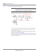
Table Of Contents
- Module Integration Guide
- Preface
- About this Guide
- Introduction
- Manufacturing Process
- Hardware Integration Recommendations
- PCB Layout Rules
- Bring-Up and Testing
- Hardware Test Preparation
- Abbreviations

HARDWARE INTEGRATION RECOMMENDATIONS
RF INTERFACE
18 PROPRIETARY MODULE INTEGRATION GUIDE
SEQUANS Communications
3.4.4.2 ESD Protection
ESD protection is a discretionary requirement and only required if necessary,
for higher ESD specifications than those provided by the VZM20Q.
It is recommended to select an ESD device with very low capacitance and
small size (0201) to prevent further RF matching compensation.
3.4.4.3 Standard Impedance Transmission Lines
There are 2 possible methods to design 50 Ohm transmission lines:
1. With the RF track on the outer metal layer both micro-strip and coplanar
types can be implemented.
2. With the RF track on an inner metal layer embedded micro-strip and
strip-line topologies can be used.
Irrespective of which one is selected the following guidelines are
recommended:
• Design the transmission line tracks appropriately wide to minimise the RF
insertion loss between the Antenna/Antenna-connector and VZM20Q. The
maximum insertion loss of the conducted path should be < 0.5dB
• Transmission lines EM fields will couple to adjacent metal layers.
For microstrip implementation, make sure that a minimum of twice the
spacing exists between transmission-line and associated GND. This clear-
ance to adjacent metal layers will ensure that the designed transmission
line impedance is not impacted.
For co-planar design, the spacing helps to define the controlled impedance.
Take special care to make the calculations correctly.
Whether these are microstrip or co-planar designed transmission lines,
make sure that the adjacent metal GND areas are connected to the GND
reference plane using periodic via connections, as to effectively terminate
these leakage EM fields.