
Integration Guide
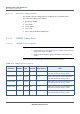
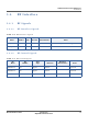
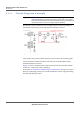
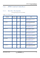
Table Of Contents
- Module Integration Guide
- Preface
- About this Guide
- Introduction
- Manufacturing Process
- Hardware Integration Recommendations
- PCB Layout Rules
- Bring-Up and Testing
- Hardware Test Preparation
- Abbreviations

HARDWARE INTEGRATION RECOMMENDATIONS
RF INTERFACE
16 PROPRIETARY MODULE INTEGRATION GUIDE
SEQUANS Communications
3.4.2 Circuit Diagram Example
Important: Figure 3-4 should be strictly followed as a topology reference. It is
recommended not to deviate from this circuit from your applica-
tion. More information is provided in this document on the layout
constraint which are too very important to abide by.
The RF inter-connect called P1 is for example purposes only. Depending on
the antenna, interfacing system will dictate the RF inter-connect.
Figure 3-2: RF Typical Circuit
LTE_ANT0 is the primary (main) antenna pin and carries TX and RX signals.
Connect 50 Ohm transmission lines from this pins to the 50 Ohm Primary
Antenna/Antenna-connector.
Figure 3-2 shows, included in the connection between ANT and the antenna
connectors, T-type network for matching.
See Section 3.4.4 Antennas and RF Design Considerations on page 17 for more
detail on connecting to these pins and for information on the T-type matching
network and ESD protection.