
Integration Guide
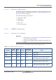
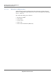
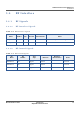
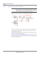
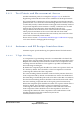
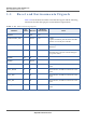
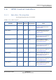
Table Of Contents
- Module Integration Guide
- Preface
- About this Guide
- Introduction
- Manufacturing Process
- Hardware Integration Recommendations
- PCB Layout Rules
- Bring-Up and Testing
- Hardware Test Preparation
- Abbreviations

HARDWARE INTEGRATION RECOMMENDATIONS
HOST COMMUNICATIONS SIGNALS
MODULE INTEGRATION GUIDE PROPRIETARY 13
SEQUANS Communications
3.3.4.2 Default Configuration
The default software configuration of UART1 is console mode. Boot traces are
sent on this interface as shown on Section 5.4.2 Confirm Module Power-Up
Operation (UART1) on page 32.
The serial link settings are as follows:
• Baud rate: 115200
• Data: 8 bits
•Parity: None
• Stop : 1 bit
•Flow control: None
3.3.5 UART2 Interface
3.3.5.1 Interface Description
Important:
• See the Section 3.3.2 General Notes on UART Connections on
page 10 for usage of UART2.
• If not used, the UART2 signals should be connected to test
points.
Table 3-7 lists the VZM20Q pins related to the UART2 interface.
Table 3-7: UART2 Interface Signals
Pin Name
Pin
Number
Trace
Style
Direction
Electrical
Characteristics
Notes
RXD2 56 Digital Out 1.8 V UART2 RXD.
TXD2 58 Digital In 1.8 V UART2 TXD
GPIO28/RTS2 10 Digital In 1.8 V UART2 RTS optional signal multiplexed
with GPIO28. Default setting is RTS.
GPIO27/CTS2 8 Digital Out 1.8 V UART2 CTS optional signal multiplexed
with GPIO27. Default setting is CTS.
GPIO26/CLK2 91 Digital In/Out 1.8 V UART2 CLK optional signal multiplexed
with GPIO26. Default setting is GPIO