
Integration Guide
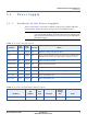
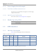
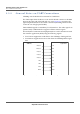
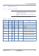
Table Of Contents
- Module Integration Guide
- Preface
- About this Guide
- Introduction
- Manufacturing Process
- Hardware Integration Recommendations
- PCB Layout Rules
- Bring-Up and Testing
- Hardware Test Preparation
- Abbreviations

HARDWARE INTEGRATION RECOMMENDATIONS
HOST COMMUNICATIONS SIGNALS
MODULE INTEGRATION GUIDE PROPRIETARY 11
SEQUANS Communications
3.3.3 UART0 Interface
3.3.3.1 Interface Description
Important:
• See the Section 3.3.2 General Notes on UART Connections on
page 10 for usage of UART0.
• If not used, the UART0 signals should be connected to test
points.
Table 3-4 lists the VZM20Q pins related to the UART0 interface.
Table 3-5: UART Interface Signals
Pin Name
Pin
Number
Trace
Style
Direction
Electrical
Characteristics
Notes
RXD0 79 Digital Out 1.8 V UART0 RXD
TXD0 77 Digital In 1.8 V UART0 TXD
RTS0 75 Digital In 1.8 V UART0 RTS
CTS0 76 Digital Out 1.8 V UART0 CTS
GPIO19/CLK0 7 Digital In/Out 1.8 V UART0 CLK optional signal multiplexed
with GPIO19. Default setting is GPIO.
GPIO41/DTR0 84 Digital In 1.8 V UART0 DTR optional signal multiplexed
with GPIO41. Default setting is GPIO.
GPIO39/DSR0 85 Digital Out 1.8 V UART0 DSR optional signal multiplexed
with GPIO39. Default setting is GPIO.
GPIO24/DCD0 88 Digital Out 1.8 V UART0 DCD optional signal multiplexed
with GPIO24. Default setting is GPIO.
GPIO25/RING0 89 Digital Out 1.8 V UART0 RING optional signal multiplexed
with GPIO25. Default setting is GPIO.