
Integration Guide
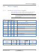
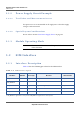
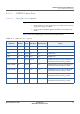
Table Of Contents
- Module Integration Guide
- Preface
- About this Guide
- Introduction
- Manufacturing Process
- Hardware Integration Recommendations
- PCB Layout Rules
- Bring-Up and Testing
- Hardware Test Preparation
- Abbreviations

HARDWARE INTEGRATION RECOMMENDATIONS
POWER SUPPLY
MODULE INTEGRATION GUIDE PROPRIETARY 7
SEQUANS Communications
3.1 Power Supply
3.1.1 Synthesis of the Power Supplies
Table 3-2 and Table 3-3 provide a synthesis of the power supplies and their
characteristics. Please see typical voltage values in VZM20Q Datasheet.
Note: Each output reference voltage (pads 3, 9, 11) can be either running
or powered off depending on the internal software configuration.
They should not be used to power external IC or parts that require
permanent supply.
Table 3-2: Power Supply Signals
Pin Name
Pin
Number
Trace
Style
Direction Notes
1V8 3 Supply Out Reference voltage. See the note above.
3V0 9,11 Supply Out To be only connected to VCC1_PA and VCC2_PA. These pads
should not be used for any other usage. See the note above.
GNSS_VCC1 100 Supply In Reserved. Do not connect.
GNSS_VCC2 101 Supply Out Reserved. Do not connect.
GNSS_VCC3 102 Supply In Reserved. Do not connect.
VBAT1 107, 108 Supply In Voltage used for qualification is 3.8 V, range 3.1 V to 4.5 V
VCC1_PA 97 Supply In To be connected to 3V0
VCC2_PA 98, 99 Supply In To be connected to 3V0
Table 3-3: Power Supply Digital Enable Signals
Pin Name
Pin
Number
Trace
Style
Direction
Typical
Voltage
Ref
Notes
POWER_EN 106 Digital In 1V8