
Data Sheet
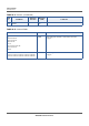
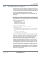
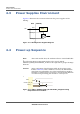
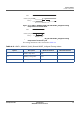
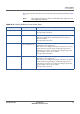
Table Of Contents
- Datasheet
- Preface
- About this Datasheet
- Product Features
- Regulatory Approval
- Physical Characteristics
- 3.1 ECCN and Part Number
- 3.2 Electrical Operating Conditions
- 3.3 Environmental Operating Conditions
- 3.4 Auxiliary ADC Specification
- 3.5 Power Supply Dimensioning
- 3.6 I/O Characteristics
- 3.7 Package Description
- 3.8 Packing Information
- 3.9 Storage Conditions
- 3.10 Mounting Considerations
- 3.11 Component Reliability
- 3.12 RF Performance
- Signals and Pins
- Acronyms

SIGNALS AND PINS
LOW POWER MODE
SP150Q DATASHEET PROPRIETARY 40
SEQUANS Communications
The signals involved in the low-power mode of the SP150Q are listed in Table
4-4.
Note: Each signal’s pull (up or down) is determined by register. It can
be modified by software.
Table 4-4: Signals Related to Low-Power Mode
Signal Name Drive Description
SDIO_HOST_D1 Open-drain Possible wakeup by SDIO Host activity.
See important note below.
USB_EXT_VBUSVLD Open-drain Possible wakeup by USB activity. USB_EXT_VBUSVLD is
driven low and indicates USB cable presence if value is 1
(based on VBUS).
See important note below.
WAKE_0
Input with pull-down
1
1. Internal pull-down resistor has 30 kOhm to 72 kOhm value.
Default setting is to wake on high to low transition.
Available for user application.
The software can configure SP150Q to wake from low power
mode when this signal is high, or when this signal is low.
Alternatively, software can configure SP150Q to ignore this
signal when it is in low power mode.
See important notes below.
WAKE_1 Input Default setting is to wake on high to low transition.
Available for user application.
The software can configure SP150Q to wake from low power
mode when this signal is high, or when this signal is low.
Alternatively, software can configure SP150Q to ignore this
signal when it is in low power mode.
See important note below.