
Data Sheet
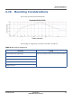
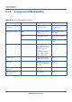
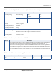
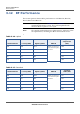
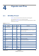
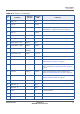
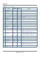
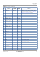
Table Of Contents
- Datasheet
- Preface
- About this Datasheet
- Product Features
- Regulatory Approval
- Physical Characteristics
- 3.1 ECCN and Part Number
- 3.2 Electrical Operating Conditions
- 3.3 Environmental Operating Conditions
- 3.4 Auxiliary ADC Specification
- 3.5 Power Supply Dimensioning
- 3.6 I/O Characteristics
- 3.7 Package Description
- 3.8 Packing Information
- 3.9 Storage Conditions
- 3.10 Mounting Considerations
- 3.11 Component Reliability
- 3.12 RF Performance
- Signals and Pins
- Acronyms

SP150Q DATASHEET PROPRIETARY 29
SEQUANS Communications
4
Signals and Pins
4.1 SP150Q Pinout
Table 4-1 lists the function and main information for SP150Q pads.
The pads listed in Table 4-2 are connected to ground.
Refer also to Figure 4-1 that represents the typical implementation for UART
hardware flow control.
Table 4-1: Pinout
Pad
#
Pad Name
Alternate
Function
Direction
(HW)
Comments
2 NETWORK_LED GPO_3,
SPI_CS_N_2
Out
3 1V8 Out Reference voltage for IOs.
Note: it can be used to provide power small devices
(50 mA max usage)
4 USB_EXT_VBUS_VLD WAKE_2 In
5 FFF_FFH GPIO_18 In - Pull-up for a system boot in FFF mode.
- Pull-down for a system boot in FFH mode.
6 ACTIVITY_LED GPO_2 Out
7 MODULE_ON_IND GPIO_19 Out Module “ON” Indicator.
8 HWID1 GPIO_27 In This signal shall be pull-up.
9 DNC/HSIC_DATA In/Out Reserved, do not connect.
10 HWID2 GPIO_28 In This signal shall be pull-up.
11 DNC/HSIC_STROBE Out Reserved, do not connect.
12 SIM_RSTN Out
13 USB_D+ In/Out