
Data Sheet
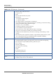
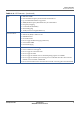
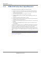

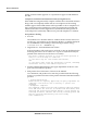
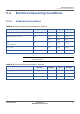
Table Of Contents
- Datasheet
- Preface
- About this Datasheet
- Product Features
- Regulatory Approval
- Physical Characteristics
- 3.1 ECCN and Part Number
- 3.2 Electrical Operating Conditions
- 3.3 Environmental Operating Conditions
- 3.4 Auxiliary ADC Specification
- 3.5 Power Supply Dimensioning
- 3.6 I/O Characteristics
- 3.7 Package Description
- 3.8 Packing Information
- 3.9 Storage Conditions
- 3.10 Mounting Considerations
- 3.11 Component Reliability
- 3.12 RF Performance
- Signals and Pins
- Acronyms

PRODUCT FEATURES
TDM-PCM INTERFACE SPECIFICATION
5 PROPRIETARY SP150Q DATASHEET
SEQUANS Communications
1.2 TDM-PCM Interface Specification
The features of the SP150Q’s TDM-PCM controller include:
• Support of PCM slave mode with PCM_CLK input and PCM_FS input.
• Support of PCM master mode with with PCM_CLK input and PCM_FS
output generated internally
• PCM_CLK input frequency from 128 kHz to 8192 kHz
• Variable number of time-slots within a frame depending on PCM_CLK
frequency
• Support of PCM data format of 8-bits or 16-bits
• In master mode, SP150Q can generate other Frame Sync periods than the
standard Frame Sync period (125 µs).
• Support of short and long Frame Sync formats (active for 1 or 3 PCM_CLK
periods)
• Separated programmable time-slot-offset value for Tx and Rx, for each
voice channel.
It supports two channels of voice over TDM-PCM. This support is provided
by having two complete PCM controllers, each with its own full register set.
These two controllers are time division multiplexed on the PCM bus.
Sequans PCM interface takes PCM_CLK as an input in both master and slave
modes. It supports a set of different frequencies, in the range 128 kHz to 8192
kHz.
Caution: This clock signal is an input in both master and slave modes.
The signals implementing the PCM interface are detailed in 4.2.2 I2S/PCM
Interface Signals on page 36.