
Data Sheet
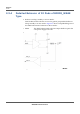
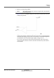
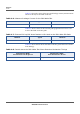
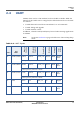
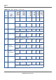
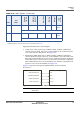
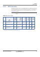
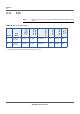
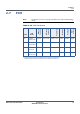
Table Of Contents

INTERFACES
UART
GM02S DATASHEET (PRELIMINARY) PROPRIETARY 15
SEQUANS Communications
High-Speed UARTs Flow Control Signals
• CTS0, CTS1, CTS2, CTS3: resp. UART0, UART1, UART2, UART3 flow
control, Clear-To-Send, active low, of the GM02S. To be connected to the
CTS of the remote UART device. See Figure 2-8.
• RTS0, RTS1, RTS2, RTS3: resp. UART0, UART1, UART2, UART3 flow
control, Ready-To-Send, active low, of the GM02S. To be connected to the
RTS of the remote UART device. Provision a 1 kOhm pull-down on RTS pin
when flowcontrol is not used. If it is connected to an external component
(like a RS232 driver), the user should make sure that this component will
present a low level to the GM02S. See Figure 2-8.
Figure 2-8 represents the typical implementation for the hardware
flowcontrol.
Figure 2-8: UART Convention and Flow Control
Note: Please refer to Module Integration Guide for details on UART
connection.
21 GPIO21/CTS3 GPIO21 CTS3 PVDD_1V8 In/Out BIDIR Out-1,
2mA
UART3
23 GPIO22/RTS3 GPIO22 RTS3 PVDD_1V8 In/Out BIDIR Out-1,
2mA
UART3
1. Alternate functions will be available in future versions via SW upgrade.
2.UART pad types’s electrical characteristics are detailed in Table 2-19.
Table 2-9: UART Signals (Continued)
Pad #
Pad
Name
Primary
Function
Alternate
Function
1
Power Group
Direction
Pad type
2
State
@reset
'DϬϮ^
ƉƉůŝĐĂƚŝŽŶ
dyϬdyϭdyϮdyϯ dy
ZyϬZyϭZyϮZyϯ Zy
Zd^ϬZd^ϭZd^ϮZd^ϯ Zd^ͺE
d^Ϭd^ϭd^Ϯd^ϯ d^ͺE