
Data Sheet
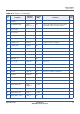
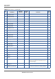
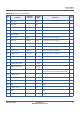
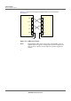
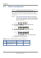
Table Of Contents
- Datasheet
- Preface
- About this Datasheet
- Product Overview
- Physical Characteristics
- Signals and Pins
- Acronyms
- PCB Layout Rules

SIGNALS AND PINS
POWER-UP SEQUENCE
31 PROPRIETARY CB410L DATASHEET
SEQUANS Communications
3.3 Power-Up Sequence
Important: The RESETN (pin 63) should be driven by the Host (active low).
This signal should be kept high (100K pull up, 1V8).
The following timing requirement applies to the signals VBAT1, VBAT2,
MODULE_PWR_EN and RESET_N. It must be respected for proper CB410L’s
behavior. The RESET_N signal is controlled automatically in case of cold start
and warm start.
Caution: VBAT1 and VBAT2 should remain stable in the voltage range
listed in 2.2 Electrical Operating Conditions on page 10; if this
condition is not met, the internal OTP (One-Time Programmable)
area of the baseband chip might be randomly corrupted and it can
lead to a non-functional and unrecoverable state preventing the
module to correctly boot.
Figure 3-2: VBAT1, VBAT2, MODULE_PWR_EN Signals Timing
Requirement for Cold Start
Figure 3-3: VBAT1, VBAT2, MODULE_PWR_EN Signals Timing
Requirement for Warm Start
Figure 3-4: VBAT1, VBAT2, MODULE_PWR_EN and RESET_N Signals
Timing Requirement for Reset Cycle
The timing minimum values are listed in Table 3-4.
9%$79%$7
02'8/(B3:5B(1
WV
D E
9%$79%$7
02'8/(B3:5B(1
9%$79%$7
02'8/(B3:5B(1
5(6(7B1
WK
F G
Table 3-4: VBAT1, VBAT2 and RESET_N Signal Timing Values
Symbol Description Minimum Duration Maximum Duration
ts VBAT1 and VBAT2 setup time 0 ms -
th1 RESET_N hold time 1 µs -