Eclipse 5™ with autoSAT® Personal Ambulatory Oxygen System (PAOS)™ PROVIDER TECHNICAL MANUAL
TABLE OF CONTENTS General Information...................................................4 Warning and Caution Statements............................................ 4 Introduction to the Eclipse 5 Oxygen System.................. 5 Power Cartridge.................................................................................21 Typical New Power Cartridge Operation Time.........21 Charging Algorithm..................................................................
TABLE OF CONTENTS (continued) Clean the Cabinet and Control Panel and Power Supplies............................................................35 Monthly Maintenance—Patient.......................................36 Care for the Power Cartridge...............................................36 Calibrating the Power Cartridge.......................................36 Patient Training Checklist.............................................................37 Annual Maintenance—Provider.............
Personal Ambulatory Oxygen System Provider Technical Manual General Information This technical manual will familiarize you with Provider-specific information regarding the Eclipse 5 Oxygen System.
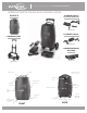
Personal Ambulatory Oxygen System Provider Technical Manual Introduction to the Eclipse 5 Oxygen System Eclipse 5 AC Power Supply WITH NEMA POWER CORD PN: 5941-SEQ DC Power Supply UNIVERSAL Cart PN: 5942-SEQ Power Cartridge (battery) PN: 7082-SEQ PN: 5991-SEQ Control Panel EDAT Service Port Handle (Not for Patient Use) Air Inlet Filter External Power Receptacle Oxygen Outlet Port FAA Approval Icon FAA Approval Icon Power Cord Retainer Rating Label & Serial Number Location Cart Attachment
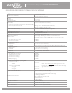
Personal Ambulatory Oxygen System Provider Technical Manual Eclipse 5 Oxygen System Specifications Oxygen Concentrator Dimensions (H x W X D) Weight Eclipse 5 Power Cartridge 19.3 x 12.3 x 7.1 inches (49.0cm x 31.2cm x 18.0cm) 15.0 pounds 3.4 pounds Flow Settings 0.5 to 3.0 LPM (0.5 liter increments) Continuous Flow (measured in Liters Per Minute LPM) Pulse Dose (measured in mL) Settings 1.0-6.
Personal Ambulatory Oxygen System Provider Technical Manual Pulse Dose Mode Specifications Pulse Settings Trigger Sensitivity Adjustable Bolus Rise Time 1.0 to 6.0, in 8mL increments up to 96 mL; 7-9 in 32mL increments up to 192 mL Adjustable between settings of 1 (most sensitive) to 3 (least sensitive) Adjustable settings of Fast(factory setting), Medium, or Slow • Cannula pressure has dropped below the trigger point (typically between 0.135—0.
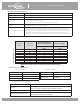
Personal Ambulatory Oxygen System Provider Technical Manual Independent Safety Testing Eclipse System and Eclipse Concentrator Safety IEC 60601-1 :1988 + A1 :1991 + A2 :1995 + Corrigendum (6/95) EN 60601-1(1990) + A1(1993) + A2(1995) + A12(1993) + A13(1996) + Corrigenda (7/94) Electromagnetic Compatibility FCC 15B (Sec.
Personal Ambulatory Oxygen System Provider Technical Manual Electromagnetic Compatibility This equipment has been tested and found to comply with the limits for medical devices to the IEC60601-1-2 Electromagnetic Compatibility standard. These limits are designed to provide reasonable protection against harmful interference in a typical medical installation.
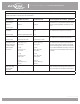
Personal Ambulatory Oxygen System Provider Technical Manual Guidance and manufacturer’s declaration–electromagnetic immunity The Eclipse 5 is intended for use in the electromagnetic environment specified below. The customer or the user of the Eclipse 5 should assure that it is used in such an environment.
Personal Ambulatory Oxygen System Provider Technical Manual Guidance and manufacturer’s declaration–electromagnetic immunity The Eclipse 5 is intended for use in the electromagnetic environment specified below. The customer or the user of the Eclipse 5 should assure that it is used in such an environment.
Personal Ambulatory Oxygen System Provider Technical Manual Recommended separation distances between portable and mobile RF communications equipment and the Eclipse 5 The Eclipse 5 is intended for use in an electromagnetic environment in which radiated RF disturbances are controlled.
Personal Ambulatory Oxygen System Provider Technical Manual How The Eclipse 5 Works Introduction The Eclipse 5, Personal Ambulatory Oxygen System with autoSAT Technology is a portable medical device used to extract oxygen from the atmosphere, concentrate it to 87–95.6% and present the oxygen to the patient. The device will operate in Continuous Flow Mode or Pulse Dose Mode. In Continuous Flow Mode the oxygen is provided at a constant flow rate between 0.5 and 3.0 LPM.
Personal Ambulatory Oxygen System Provider Technical Manual Compressor and Compressor Enclosure The Eclipse 5 Compressor is a two-cylinder, variable speed wobble piston compressor, driven by a highly efficient Brushless DC (BLDC) motor. When air flows into the Compressor enclosure, it passes through an air intake filter/muffler that muffles sound and filters out impurities. Using one cylinder, the compressor takes in filtered air and delivers it to the ATF Module under pressure.
Personal Ambulatory Oxygen System Provider Technical Manual Control Panel The control panel provides a user interface consisting of a membrane panel keyboard, Liquid Crystal Display (LCD), external power present indicator, Power Cartridge capacity indicator, alarm status indicators, and an audio transducer. The user interface informs the user of the system status and allows the user to set the desired flow rate and flow mode.
Personal Ambulatory Oxygen System Provider Technical Manual User Controls And System Status Indicators, cont. Symbol Definition Symbol Definition No Smoking Icon (button): Do not smoke near unit. Providers can access provider mode software functions using the Control Panel. All provider mode information is displayed on the LCD. The software shall advance the following Eclipse 5 display mode when the “No Smoking” icon is pressed (see pg. 15). FAA approved for use aboard passenger aircraft.
Personal Ambulatory Oxygen System Provider Technical Manual Continuous Flow Mode Continuous Flow Mode delivers a constant flow of oxygen to a patient by means of tubing and a nasal cannula at rates between 0.5 LPM and 3.0 LPM. Within the Eclipse 5, concentrated oxygen is stored in a 500ml product tank at pressures in the range of 5 to 9 psi. This pressure gives Continuous Flow Mode the capability to deliver the indicated flow rate to the patient even if extension tubing is used, up to 50 feet long.
Personal Ambulatory Oxygen System Provider Technical Manual Provider Mode Functions Providers can access provider mode software functions using the Control Panel. All provider mode information is displayed on the LCD. The software shall advance the following Eclipse 5 display mode when the “No Smoking” icon is pressed: • Alarm Code (ALRM) - Displays most recent alarm code. Additional alarm codes will also be displayed, if present, by continuing to press the + key.
Personal Ambulatory Oxygen System Provider Technical Manual Service Mode Functions Factory maintenance or service updates may sometimes be required on the Eclipse 5. Factory and qualified factory-trained technicians can access service mode software functions by using the Service Port located on the back of the unit. The Service Port is not for patient use.
Personal Ambulatory Oxygen System Provider Technical Manual Power Supplies The Eclipse 5 may operate from either the AC or DC Power Supply or the Power Cartridge. When power is available from an external supply, the Eclipse 5 will draw from the external source rather than depleting the Power Cartridge. Connection to external power is indicated when the External Power Present Indicator located on the Control Panel is illuminated.
Personal Ambulatory Oxygen System Provider Technical Manual Figure 6: Eclipse 5 DC Power Supply Located near the output cord, there is a green LED that is illuminated when the DC Power Supply is supplying 26VDC power. If the LED is not illuminated, there is no input power available. The Power Supply contains protection circuits for output overcurrent, input over-voltage, and internal over-temperature conditions. If any of these conditions exist, output power will be interrupted and the LED will turn off.
Personal Ambulatory Oxygen System Provider Technical Manual The Eclipse 5 Power Cartridge operation time may be affected by several factors such as bolus size, breathing rates, ambient temperature, age of power cartridge and use over time. The table below describes the typical operating time for a new Power Cartridge. If the Eclipse 5 is used in Pulse Dose Mode, there will be longer operating time. The patient should consult their physician for a prescription for Pulse Dose Mode.
Personal Ambulatory Oxygen System Provider Technical Manual WARNING: DO NOT tamper with, disassemble, crush or heat the Power Cartridge above 140° F (60° C). The Power Cartridge may present a risk of fire or explosion and will void the warranty. CAUTION Store the Power Cartridge in a cool, dry place when not in use. CAUTION CAUTION DO NOT leave the Eclipse 5 or the Power Cartridge in a vehicle or in the trunk during a hot or cold day. The Eclipse 5 system can only work with a CAIRE Power Cartridge.
Personal Ambulatory Oxygen System Provider Technical Manual Charging Algorithm The charging algorithm is performed by the Power Manager software and involves three basic decisions: 1. 2. 3. When to start charging How fast to charge When to stop charging Charging begins when Power Cartridge voltage falls below 16.0 volts. The charging current is limited by the charger capability and the rated capacity of the Power Cartridge.
Personal Ambulatory Oxygen System Provider Technical Manual Training The Patient Introduction Welcome to the Eclipse 5, Personal Ambulatory Oxygen System with autoSAT Technology. Setting up and training your patient to use the Eclipse 5 has never been easier! You can expect your patients and care providers to easily learn how to use the device by following the directions in this section. While setting up and training a patient, be sure to point out the advantages of the Eclipse 5.
Personal Ambulatory Oxygen System Provider Technical Manual Indications for Use The Eclipse 5 is indicated for the administration of supplemental oxygen. The device is not intended for life support nor does it provide any patient monitoring capabilities. A physician must prescribe a specific oxygen flow rate setting to meet patients’ individual needs. Recommended oxygen flow rates should be adjusted only under the advice of a physician.
Personal Ambulatory Oxygen System Provider Technical Manual WARNING: No Smoking or Open Flames. For safety concerns, all possible sources of ignition must be kept away from the oxygen system and preferably out of the room in which it is being used. Smoking in the proximity of an operating oxygen concentrator is dangerous and can permanently damage the device and void the warranty. Keep the Eclipse 5 at least five (5) feet (1.5 m) from heat sources, sparking objects or open flames.
Personal Ambulatory Oxygen System Provider Technical Manual Showing Power Cartridge Power Level The display on the Control Panel shows the amount of Power Cartridge capacity available and waterfalls when charging. Point out the table showing typical new Power Cartridge duration-of-use time in the Users Manual. WARNING: The display gives an approximate level of remaining battery power.
Personal Ambulatory Oxygen System Provider Technical Manual ‘power cartridge (Battery) Conservation’ feature While in Pulse Dose Mode, the Eclipse 5 is always monitoring for breath detection. After 15 seconds of no breath detected, the Eclipse 5 “delivers” Continuous Flow at the last Continuous Flow setting. The system and display are still in Pulse Dose Mode and the green Delivery Mode Indicator is blinking fast, indicating you are receiving a Continuous Flow.
Personal Ambulatory Oxygen System Provider Technical Manual Adjusting rise time The adjustable Rise Time feature on the Eclipse 5 was designed for patient comfort. The Rise Time feature adjusts flow and speed of bolus delivery, and determines how quickly the patient receives their bolus volume while in Pulse Dose Mode. The Eclipse 5 offers delivery settings of fast, medium, and slow. The factory default setting is FAST.
Personal Ambulatory Oxygen System Provider Technical Manual Connecting the DC Power Supply To install the DC Power Supply, follow these steps: A DC Power Supply allows the system to operate from DC outlets, such as those found in motor vehicles. CAUTION The DC Power Supply is designed for 12VDC minimum vehicle electrical systems. Do not attempt to operate with 6V, 24V, or other vehicle electrical system. 1.
Personal Ambulatory Oxygen System Provider Technical Manual CAUTION NOTE: Always check to see that the Air Inlet and the Exhaust Vent are not blocked and the Air Inlet Filter is dry and clean before using your Eclipse 5. • Do not drop the Eclipse 5 or Eclipse 5 power supplies. If dropped or damaged, verify unit performance. • The Eclipse 5 will not detect a cannula that has been disconnected from the Oxygen Outlet Port.
Personal Ambulatory Oxygen System Provider Technical Manual CAUTION WARNING: • • • Be sure to accurately determine the amount of current the vehicle accessory outlet is rated to supply. Avoid placing the Eclipse 5 in direct sunlight. Do not store the Eclipse 5 in a vehicle where the device may be subject to extreme temperatures. Extreme heat or cold may impair operation and damage the device and degrade the Power Cartridge.
Personal Ambulatory Oxygen System Provider Technical Manual Traveling by Air TRAVEL APPROVED The Eclipse 5 is an FAA approved portable concentrator. A new US Department of Transportation regulation regarding portable oxygen concentrators took effect on May 13, 2009. Under this regulation, every FAA approved portable concentrator is now authorized for use during any commercial flight that departs or arrives in the USA, regardless of whether the airline itself has approved the device or not.
Personal Ambulatory Oxygen System Provider Technical Manual Eclipse 5 maintenance Weekly Maintenance—Patient Training your patient to maintain the Eclipse 5 properly will lead to longer service intervals and lower maintenance costs. Train your patient to perform the following procedures: Clean the Air Inlet Filter The Air Inlet Filter, located at the rear of the unit, must be cleaned at least once a week. To clean the filter: 1. Remove the filter from the back of the cabinet. 2.
Personal Ambulatory Oxygen System Provider Technical Manual MOnthly Maintenance—Patient Care for the Power Cartridge The Power Cartridge (battery) in the Eclipse 5 requires special care to assure a longer life and the highest level of performance. The CAIRE Power Cartridge is the only approved Power Cartridge recommended for use with the Eclipse 5.
Patient Training Checklist Use the following checklist as a guide to assist in setup and training a patient on the use of the Eclipse 5™ with autoSAT® Technology and its accessories.
Personal Ambulatory Oxygen System Provider Technical Manual Annual Maintenance—Provider Introduction Properly maintaining the Eclipse 5 will ensure longer life and higher performance. Minimum annual maintenance is required. CAUTION The Eclipse 5 contains electrostatic sensitive components. Do not open or handle except at a static free workstation. Do not remove cover without ESD protection.
Personal Ambulatory Oxygen System Provider Technical Manual Annual Maintenance Procedures The following section lists procedures that are necessary to maintain the Eclipse 5. Service should only be performed by a qualified technician. To perform periodic maintenance, the only tools that should be necessary are: • • • • #1 Phillips Screwdriver Wire-cutting pliers Small cable ties ESD Mat or approved ESD system Figure 11: Maintenance Tools. Removing the Unit Cover 1.
Personal Ambulatory Oxygen System Provider Technical Manual CAUTION The Eclipse 5 contains electrostatic sensitive components. Do not open or handle except at a static free workstation. Do not remove cover without ESD protection. Screws Figure 12: Removing screws to open the Front Cover 4. Turn over and place the unit horizontally on the back cover. 5. Remove the front cover -- pop the bottom end off first and rotate it towards the handle.
Personal Ambulatory Oxygen System Provider Technical Manual 6. Disconnect the cable from the Control Panel as follows: a. b. c. Grasp the circuit board firmly between your fore fingers and thumb. Grasp the head of the Membrane Panel Overlay cable in your other hand. Firmly pull the cable away from the board. Pull the cable straight out. Do not rock the connector back and forth. This may damage the pins of the header.
Personal Ambulatory Oxygen System Provider Technical Manual Cut Cable Tie Figure 15: Disconnecting the Oxygen Outlet Tube 8. Lay the front panel away from Eclipse 5. Inspect PEM Nut anchors in the front cover assembly. Perform necessary maintenance. Figure 16: Front Cover Removal Once the cover has been removed, the procedures listed in this section may be performed.
Personal Ambulatory Oxygen System Provider Technical Manual Remove and Replace 9 Volt Battery Replace the 9-volt battery when the unit beeps three times at the end of power-on self-test, when voltage is less than 7.0 Volts, or during annual PM. To replace the 9-volt battery, follow these steps: WARNING: Disconnect power supplies and remove Power Cartridge before removing the unit cover. Do not touch exposed circuits during maintenance without ESD protection. 1. Remove the Eclipse 5 front cover assembly.
Personal Ambulatory Oxygen System Provider Technical Manual Remove and Replace HEPA Filter Replace the HEPA filter annually, or more often as needed. To replace the HEPA filter, follow these steps. WARNING: NOTE: DO NOT use any petroleum based or other lubricants. A spontaneous and violent ignition may occur if oil, grease or other petroleum substances come into contact with oxygen under pressure. Keep these substances away from the oxygen system, tubing and connections and any other oxygen source.
Personal Ambulatory Oxygen System Provider Technical Manual 2. Unscrew the wing nut that holds the HEPA filter. Figure 20: Wing Nut. 3. Unscrew the Clear HEPA filter and discard filter & small o-ring. Figure 21: Unscrewing the HEPA Filter. 4. Install the new small o-ring and HEPA filter. Figure 22: Installing the new HEPA Filter.
Personal Ambulatory Oxygen System Provider Technical Manual 5. Locate the large o-ring on the product tank, replace it with the new large o-Ring included in the PM kit (5022-SEQ). Screw the new HEPA filter into the carriage holder (wing nut topped housing). Insert and screw the new HEPA filter (wing nut topped housing) into the carriage holder (product tank) and finger snug in place (do not over-tighten). Re-attach tubing and secure with a cable tie. Figure 23: O-Ring.
Personal Ambulatory Oxygen System Provider Technical Manual To replace the compressor intake filter, follow these steps: 1. Cut the cable tie on the silicone tubes attached to the compressor intake filter. Figure 24: Removing the Compressor Intake Filter. 2. Remove the silicone tubes attached to each end of the filter body. 3. Install a new filter by pushing each tube completely over the barb on the filter body. Verify flow direction is correct. 4. Reconnect silicone tubes to the filter.
Personal Ambulatory Oxygen System Provider Technical Manual After replacing the Compressor Intake Filter, check the following: • Verify proper seating of the filter in the Eclipse 5. The arrow on the filter body should point toward the 9-volt battery. • Ensure that the inlet tube is inserted securely into its hole in the compressor box and is not pinched.
Personal Ambulatory Oxygen System Provider Technical Manual Test Procedures Purity and Flow Rate Test Procedure - Preferred Method It is recommended that the Eclipse 5 be tested for oxygen concentration and flow performance. The CAIRE recommended test setup is shown on the following diagram. Oxygen monitors may or may not have an internal pump to draw samples of oxygen to be measured. Placement of the oxygen monitor in the test setup depends whether they have an internal pump.
Personal Ambulatory Oxygen System Provider Technical Manual Assembly and Alarm Verification Tests To ensure proper assembly and functionality of the Eclipse 5 after it has been reassembled, the following steps should be followed. 1. Install the Power Cartridge into the Power Cartridge compartment of the Eclipse 5. Plug the AC Power Supply into the wall outlet and connect it to the External Power Connector of the Eclipse 5. 2. Press the ON button and set the Eclipse 5 to 2 LPM.
Personal Ambulatory Oxygen System Provider Technical Manual Record Hours of Operation & Software Version To help maintain the Eclipse 5, you may obtain the Total Hours of Operation and software version numbers for the Control Board and the Power Manager Systems by following the steps below.
Personal Ambulatory Oxygen System Provider Technical Manual Electrical Safety Test This is required only for the Eclipse 5 Oxygen System, that is used in a hospital or institutional environment. This is not required for home care use. To test the basic electrical safety of the Eclipse 5 AC Power Supply, CAIRE recommends using an LKG-601 Electrical Safety Analyzer (Netech Corporation, Hicksville, NY) or equivalent to verify that the current leakage to ground is within appropriate limits. 1.
Personal Ambulatory Oxygen System Provider Technical Manual Provider Service and Maintenance Record Whenever maintenance or service is performed on an Eclipse 5 unit, an entry should be made in the service log for that concentrator or recorded in accordance with your company’s standard procedure. Whenever the case of the Eclipse 5 is opened, the flow rate, purity, and alarm status should be verified per the Test Procedures in this manual.
Personal Ambulatory Oxygen System Provider Technical Manual Shipping and Transporting the Eclipse 5 When shipping the Eclipse 5 use original packaging, if possible. Always remove the Power Cartridge and cart from the Eclipse 5 prior to shipping. If original packaging material is available repack the Eclipse 5, Power Cartridge, cart and power supplies in the designated packaging areas.
Personal Ambulatory Oxygen System Provider Technical Manual Troubleshooting, Service, and Repair Procedures CAUTION NOTE: The Eclipse 5 contains electrostatic sensitive components. Do not open or handle except at a static free workstation. Do not remove cover without ESD protection. To adequately troubleshoot and repair the product in the field, EDAT is recommended.
Personal Ambulatory Oxygen System Provider Technical Manual System Troubleshooting and Alarms PROVIDER TROUBLESHOOTING TABLE DO NOT Ignore Alarms. Yellow Light Symptom Alarm Code Possible Cause Provider Action The yellow light is on solid. There is no audible alarm. (This alarm may occur with 001 or 100 the Eclipse 5 off while the battery is charging as well) 1) Remove power cartridge and re-install to ensure that it is secure in the concentrator.
Personal Ambulatory Oxygen System Provider Technical Manual Red Light Symptom Alarm Code The red light is flashing. The alarm is giving 3 beeps 004 every 2 minutes. The red light is solid. The alarm is giving a constant beep. The Eclipse 5 is not delivering oxygen and it will not power on. Possible Cause The Eclipse 5 has detected low oxygen levels Your Action 1) Ensure the air intake filter is not clogged or restricted. Clean and replace the filter if necessary.
Personal Ambulatory Oxygen System Provider Technical Manual Other Alarm Conditions (Continued) Symptom Alarm Code Possible Cause Your Action The Eclipse 5 is not receiving power from the attached power supply. 1) Verify that the outlet is providing power. Do not connect the power supply to a dimmer circuit or a power strip. 2) Check that cable connections on power supplies are secure to the wall/vehicle and concentrator.
Personal Ambulatory Oxygen System Provider Technical Manual Alarm Conditions and Alarm Codes Use the table below to decode Eclipse 5 alarm conditions. If other alarm codes are displayed by the Eclipse 5, contact Chart Technical Support for assistance. Note: The following table is intended as a guide for the provider, not the user. CONDITION ALARM CODE ALARM DISPLAY GREEN INDICATOR YELLOW INDICATOR RED INDICATOR AUDIBLE ALARM WHAT TO DO “Warming Up. Please Wait.
Personal Ambulatory Oxygen System Provider Technical Manual malfunction codes If a malfunction occurs in the Eclipse 5, the device will stop, the Red LED on the front panel will light and the buzzer will sound for 10 seconds and then silence.
Personal Ambulatory Oxygen System Provider Technical Manual System Schematics and Diagrams Simplified Block diagram Figure 28: Eclipse 5 Oxygen System Simplified Block Diagram. Figure 29: Top Case Components.
Personal Ambulatory Oxygen System Provider Technical Manual Control Board ATF Module Compressor Intake Filter Compressor Box Product Tank Power Manager PC Board Exhaust Duct Battery Bridge PC Board Figure 30: Bottom Case Components PN 20631679 Rev D 62
Personal Ambulatory Oxygen System Provider Technical Manual Oxygen Circuit Remove and Replace the ATF Module NOTE: There are no serviceable parts inside the ATF Module. Do not attempt to disassemble or modify the ATF Module. 1. Remove the Unit Cover as described in the section Remove and Replace the Unit Cover. 2. Cut the cable tie as shown below, and disconnect the silicone tube that goes into the product port of the ATF; this tube comes from the Product Tank. 3. Install port cap.
Personal Ambulatory Oxygen System Provider Technical Manual 5. Cut the cable ties to the braided tubes that connect into the ATF pressure and vacuum ports as shown in Figure 32. Disconnect the braided tubes. 5a. Install port caps. 6. Unscrew the 3 screws (M4x16 Pan Head Machine Screw, P/N 6961-416-SEQ) and remove the screws and washers (M4 Flat washer, P/N 6985-04-SEQ) as shown below. Remove Screws Figure 33: Remove ATF Module from Eclipse 5 Case. 7. Lift the ATF. Take off the 3 grommets.
Personal Ambulatory Oxygen System Provider Technical Manual 16” Silicone Tube Routing Figure 35: Tube Routing under ATF Module. 10. Place the ATF in the Unit Case and remove the caps from the ATF Ports. Install the Braided Tubes into the ATF pressure and vacuum ports as shown on Figure 32. Do not use oil or grease if the tubing is difficult to install. Secure joints with cable ties. WARNING: NOTE: DO NOT use any petroleum based or other lubricants.
Personal Ambulatory Oxygen System Provider Technical Manual 12. Remove caps from ATF Module. 13. Connect the silicone tube from the Product Tank into the product port of the ATF and secure joints with cable ties as shown on Figure 31. 14. Use cable tie to secure the silicone tube to the braid tube to ensure that there is NO kinking on the bend as shown on Figure 32. Hand-tighten the cable tie. Inspect the tubing to ensure the tubing is not kinked. 15.
Personal Ambulatory Oxygen System Provider Technical Manual Remove and Replace the Product Tank Assembly (PN 4378-SEQ) Removal of Product Tank 1) Follow the steps to Removing the Unit Cover 2) Remove the Front Cover Assembly completely; disconnect outlet tubing and front membrane ribbon cable. Set aside. 3) Locate the Product Tank and cut the cable ties from the ATF to the product tank (Bottom), and O2 out from the outlet connector (Top). Remove tubing from ATF to lower product tank barb. See Figure 36.
Personal Ambulatory Oxygen System Provider Technical Manual Install new Product Tank 1) Locate all parts needed: Product Tank, Product Tube from ATF (correct version), Securing arm and screws. See Figure 38. Figure 38: New product tank 2) Position the product tank with the 2 hose barbs facing in the direction of the ATF. Refer to Figure 39.
Personal Ambulatory Oxygen System Provider Technical Manual 3) Install the securing arm over the product tank, and locate the screw hole on the back case cover to secure the product tank. Install securing arm and install two screws Figure 40: Install securing arms 4) Locate the correct Product Tube - remove black ATF outlet barb cap, and attach the Product Tube Assy to the ATF output barb, secure with a cable tie. Attach the other end of the Product Tube to the Bottom port on the Product Tank.
Personal Ambulatory Oxygen System Provider Technical Manual Electronics Remove and Replace the Control Board Assembly CAUTION NOTE: 1. The Eclipse 5 contains electrostatic sensitive components. Do not open or handle except at a static free workstation. The Control Board Assembly is factory calibrated as a single unit. Do not disassemble the Control Board Assembly. Remove the Unit Cover as described in the section Remove and Replace the Unit Cover.
Personal Ambulatory Oxygen System Provider Technical Manual 4. Lift the Control Board out of the Unit. Cut the green cable tie to the silicone tube that is connected to the sensor as shown in Figure 42. Disconnect the silicone tube that is attached to the sensor. Cut the green cable ties to the silicone tubes that are connected to the flow tube as shown in Figure 42. Disconnect the silicone tubes that are attached to the flow tube. 5.
Personal Ambulatory Oxygen System Provider Technical Manual Remove and Replace the Buzzer Wire Harness 1. Unplug the buzzer from the Control Board PC Board. 2. Remove the Control Board. 3. To remove the buzzer from the case, cut the cable tie, grasp the buzzer body with a pair of pliers and rotate the buzzer to break the adhesive joint. 4. To install a new buzzer, apply a ring of cyanoacrylate adhesive (Super Glue) around the inlet hole as shown in Figure 44.
Personal Ambulatory Oxygen System Provider Technical Manual Control Board Connector Diagram Use the figure below as an aid to ensure proper connection of wire harnesses to the Control System printed circuit board.
Personal Ambulatory Oxygen System Provider Technical Manual Remove and Replace Power Manager Printed Circuit Board 1 Remove and Replace Combo Power Manager board set WARNING: CAUTION Disconnect power supplies and remove Power Cartridge before removing the unit cover. Do not touch exposed circuits during maintenance without ESD protection. The Eclipse 5 contains electrostatic sensitive components. Do not open or handle except at a static free workstation. 1.
Personal Ambulatory Oxygen System Provider Technical Manual 1.4 Unscrew the 2 Cooling Fan screws (PN: 6961-21-SEQ) holding the fan in place. Remove the Fan (PN: 1074-SEQ). Set aside for later installation. 1.5 Remove the Exhaust tube in Figure 49. Set aside for later installation. Exhaust Tube Fig 49: Exhaust Tube 1.6 Pull the Power Manager pcb 1” out of the case. Gently push the compressor box away from the Power Manager pcb about 1/8”.
Personal Ambulatory Oxygen System Provider Technical Manual 1.7 Unbox the SP5932-4-SEQ and account for all parts (Fig 51). Fig 51: New Power Manager 1.8 Position the Power Manager PCB (PN: SP5932-4-SEQ) 1” out of the case as shown in Fig 52. Gently push the Compressor Box away from the Power Manager pcb by 1/8”. Connect the 2 wire harnesses (Ext Power & ATF harness) and the Control Board Ribbon Cable. Note: Route the wiring under the edge of the compressor.
Personal Ambulatory Oxygen System Provider Technical Manual 1.8 Install the Cooling Fan (PN: 1074-SEQ) with the 2 screws (PN: 6961-210-SEQ) and lightly tighten as shown in Fig 53. Apply Loctite 425 thread locker on the tips of the threads before installing. Note: Ensure the cooling fan is blowing toward the circuit board as indicated by the arrow on the side of the fan. Fig 53: Cooling Fan placement 1.9 Turn the device over and align the BBB with the holes in the case.
Personal Ambulatory Oxygen System Provider Technical Manual Compressor As with any concentrator, the compressor is a limited-wear component and may require servicing during the lifetime of the device. The point of service will be dependent on factors such as operation time, flow settings and environmental conditions. Service is required when oxygen purity and/or flow rates cannot be maintained. Remove and Replace the Compressor Box NOTE: 1.
Personal Ambulatory Oxygen System Provider Technical Manual 3. Disconnect the 3 wire harnesses shown in Figure 56. Compressor Signal Wire Harness Blower Wire Harness Compressor Power Wire Harness Figure 56: Compressor Box electrical connections. 4. Remove the Exhaust Tube as shown in Figure 57. Verify Engagement During Installation Exhaust Tube Exhaust Duct Figure 57: Exhaust Tube Removal.
Personal Ambulatory Oxygen System Provider Technical Manual 5. Cut the three cable ties shown in Figure 58. Disconnect the two braided hoses from the pressure and vacuum ports of the ATF. Cap the three ATF module ports using tight fitting vinyl caps or vinyl electrical tape. CAUTION Once the braided hoses are disconnected from the ATF Module the ATF Module is exposed to the atmosphere.
Personal Ambulatory Oxygen System Provider Technical Manual 6. Turn the unit over onto a padded ESD safe surface and remove the 4 screws (M4x16 Pan Head Machine Screw, PN 6961-420-SEQ) and washers (M4 Flat Fender Washer, PN 3568-SEQ) shown in Figure 59. Screws Washers (4 Places) Figure 59: Remove Compressor Box screws. 7. Remove the Compressor Box. NOTE: There are no field serviceable parts inside the Compressor Box. Do not attempt to disassemble or modify the Compressor Box in the field. 8.
Personal Ambulatory Oxygen System Provider Technical Manual Maintenance and Replacement Parts Preventative Maintenance Parts Description Preventive Maintenance Kit (includes * items) * Air Inlet Filter * Compressor Intake Filter * HEPA Filter (Old /New) * 9V Battery * Wire Ties (Qty 10) EDAT (Service Tool) CAIRE Inc.
Personal Ambulatory Oxygen System Provider Technical Manual Optional Accessories Visit us at www.sequal.com for more information about optional accessories. There are many different types of oxygen tubing, cannula, and humidifiers. The following items are recommended by CAIRE Inc. for use with the Eclipse 5. Salter Labs® Humidifier, Part Number 7600, or equivalent: If your physician has prescribed an optional humidifier, follow the manufacturer’s instructions for use.
Personal Ambulatory Oxygen System Provider Technical Manual CAIRE Inc. Customer Service Contact Information If you need any additional assistance, contact CAIRE Inc: By mail: CAIRE, Inc. 2200 Airport Industrial Drive, Suite 500 Ball Ground, GA 30107 USA By telephone: 800.482.2473 By E-mail: techservice.usa@chart-ind.com www.sequal.com Authorized European Union Representative: Medical Product Services GmbH Borngasse 20 35619 Braunfels, Germany E-mail: techservice.europe@chart-ind.com www.sequal.