
User's Manual
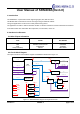

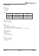
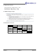

Table Of Contents
- User Manual of SRM200A(Rev1.0)
- 1. Introduction
- 2. Hardware Architecture:
- 2.1 Main Chipset Information
- 2.2 Circuit Block Diagram
- Figure 1-1 SRM200A block diagram and System Interface
- 3. Operational Description
- 3.1 Features
- 3.2 Time base of the RF frequency
- 3.3 Transmission
- 3.4 Receiver
- 3.5 Product Details
- 3.6 Output Power tolerance
- 3.7 SRM200A Category of signal
- 3.8 Simultaneous transmission

User Manual of SRM200A(Rev1.0)
1. Introduction
The SRM200A is a quad mode module supporting Sigfox, BLE, WiFi and GPS.
This Module able to transmit and receive messages using the SIGFOX network.
The typical applications can be used as a low power tracking device.
The application use WIFI or GPS to determine location. It will then transmit the location information via SIGFOX.
It also will transmit other information like temperature, accelerometer, and so on.
2. Hardware Architecture:
2.1 Main Chipset Information
Item Vendor
Part Number
SigFox
BLE
WIFI
GPS(GLONASS)
STMicroelectronics
NORDIC semiconductor
ESPRESSIF
UBLOX
S2-LP
nRF52832
ESP8285
UBX-G8020
2.2 Circuit Block Diagram
The major internal and external block diagram of SRM200A is illustrated in Figure 1-1.
BLE
nRF52832
Load
Switch
WiFi
GPS
Accelerometer
Load
Switch
Load
Switch
VDD_1
VDD_2
VDD
V_CTRL0
V_CTRL1
V_CTRL2
VDD_0
UART0
RF I/O
RF I
BATTERY
RF I/O
SWD_SFX
RESET_SFX
I2C0_ACC
VDD
VDD_0
VDD_1
VDD_2
VDD_0
VDD_2
VDD_1
V_CTRL[2:0]
SPI0
SIGFOX
SPI_BNRG
RF I/O
MCU
BLUE NRG-2
EEPROM
UART[1:0]
VDD
VDD
UART1
UART_WIFI
RESET_WIFI
DL_EN
I2C0
RESET_BLE
GPIO x 11
SWD_BLE
V_BCKP_GPS
VDD_0
VDD_0
Figure 1-1 SRM200A block diagram and System Interface
Version 1.0 SEONG JI page 1 of 11