
Specifications


Page 51 /148
2.7.4 ATM Traffic Shaping
The Mxxx ATM interfaces have their own support for traffic shaping on a per
virtual circuit (VC) basis. Specifically, in Variable Bit Rate (VBR) mode, the ATM
PICs support per VC configuration of the peak cell rate, sustained cell rate, burst
size, and queue length. Typically, the Mxxx will transmit at the sustained cell
rate. The peak cell rate represents the maximum rate to which the VC may burst
and the burst size specifies the length of time during which the VC is allowed to
transmit at peak rate. The queue length is also configurable, to keep slower VCs
from queuing packets to the point of filling up all available memory on the PIC. It
also allows you to control the queue latency through the box.
The Mxxx also supports Constant Bit Rate (a special case of VBR where peak
rate = cell rate and burst = 0) and Unspecified Bit Rate, where no VC
transmission limits are imposed.
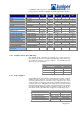
ATM Interfaces: Traffic Shaping Parameters
Per VC Variable Bit Rate (VBR) transmit configuration
Peak Cell Rate
Sustained Cell Rate
Burst Size
Queue Length (ensures that slower VCs don’t dominate buffers)
Constant Bit Rate (CBR) Supported
Peak Rate = Sustained Rate, Burst = 0
Unspecified Bit Rate (UBR) Supported
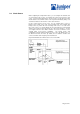
You can smooth the traffic using VBR traffic shaping. You can configure a traffic-
shaping profile that defines the bandwidth utilization, which consists of the peak
cell rate, the sustainable cell rate, and the burst tolerance, and that defines the
maximum queue length. These values are used in the ATM generic cell-rate
algorithm, which is a leaky bucket algorithm that defines the short-term burst rate
for ATM cells, the maximum number of cells that can be included in a burst, and
the long-term sustained ATM cell traffic rate. Each individual VC has its own
independent shaping parameters.
The Mxxx ATM interfaces have their own support for traffic shaping on a per
virtual circuit (VC) basis. For ATM, queuing is done on the ATM PIC itself so that
cell transmission and reception follow the CoS rules on a per VC basis.
16-MB SDRAM memory is available for the ATM SAR on the ATM PIC. On the
OC-3 PIC, which has two ports, it is 8MB per port since the 16MB is split between
the ports. The cell buffers are located on the ATM PIC. Per-VC queuing is
supported. The buffers are allocated per VC.
VBRnrt is supported on the ATM PIC. Currently VBRrt and ABR are not
supported. VBRrt can be approximated by adjusting the depth of the VC queue.
Specifically, in Variable Bit Rate (VBR) mode, the ATM PICs support per VC
configuration of the peak cell rate, sustained cell rate, burst size, and queue
length. Typically, the M40/M20 will transmit at the sustained cell rate. The peak
cell rate represents the maximum rate to which the VC may burst and the burst
size specifies the length of time during which the VC is allowed to transmit at
peak rate. The queue length is also configurable, to give you the ability to keep
slower VCs from queuing packets to the point of filling up all available memory on
the PIC. It also allows you to control the queue latency through the box.
You can configure a traffic-shaping profile that defines the bandwidth utilization,
which consists of the peak cell rate, the sustainable cell rate, and the burst
tolerance, and that defines the maximum queue length. These values are used in
the ATM generic cell-rate algorithm, which is a leaky bucket algorithm that
defines the short-term burst rate for ATM cells, the maximum number of cells that
can be included in a burst, and the long-term sustained ATM cell traffic rate. Each
individual VC has its own independent shaping parameters.
By default, the bandwidth utilization is unlimited. That is, unspecified bit rate
(UBR) is used. Also, by default, buffer usage by VCs is unregulated.