
Specifications


Page 41 /148
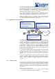
The cells are then reassembled in the I/O Manager ASIC on the outgoing FPC
and passed to the chip on the PIC for encapsulation and transmission.
The pooled memory source is deliberately oversized, and is comprised of
memory provided by all available FPCs. The size of the memory pool ensures
that each cell is never held up waiting for available buffer memory, and therefore
the forwarding process is never unduly interrupted or delayed. Automatic
redundancy is provided, should a FPC’s memory fail, by virtue of the fact that the
memory is a pooled resource. No cell is held up waiting or tied to a specific FPC
before it can be processed.
Route lookups and forwarding instructions to output queues are handled by a
dedicated lookup engine. No routing control background process can interfere
with the forwarding process.
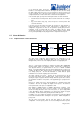
The outgoing cells are reassembled into a packet, for outbound transmission just
prior to transmission to the output port. The queuing discipline is implemented in
the I/O Manager ASIC as four packet pointer queues per physical port (e.g. each
OC-3 SONET port on a 4xOC-3 PIC would have its own set of queues). These
queues are serviced in a weighted round robin fashion. Queue selection is based
on parameters in the packet and the results of the forwarding decision.
Congestion control is implemented by a RED implementation, with three separate
drop profiles. The drop profile can be selected based on the transport layer
protocol or based on the traffic policing mechanisms on the input port.
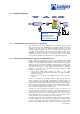
2.5.5 The Routing Engine
The Routing Engine (RE) is the component of the system that performs the
routing function. The RE is a PCI-based Pentium platform running a UNIX-like
operating system optimized to support a large number of interfaces and large
routing and forwarding tables. The RE is connected to the Packet Forwarding
Engine (PFE) through a 100-Mbps channel. The RE constructs the PFE’s
forwarding table. The PFE’s forwarding table is what is used to forward all
packets transiting through the router. The RE constructs the forwarding table
based on information from several sources: addresses of local interfaces, static
routing configuration and dynamic routing and signaling protocols. Junos has an
idea of a preference for a prefix. The preference is the value used in calculating
the forwarding table when candidate paths for that prefix are found in multiple
routing protocols. Some protocols, such as BGP, allow the preference to be
configured per-prefix while other protocols, such as IS-IS, are configured with a
preference value to apply to all routes.
In an environment where a M20/M40/M160 is configured to exchange routing
information through dynamic protocols such as BGP and IS-IS, routing messages
that arrive on the PFE’s interfaces must be sent up to the RE. A packet
containing a routing message for the local system is received just like all other
packets. Specifically, the packet is received and immediately buffered. In
parallel with the buffering, a route lookup is done. It is at the route-lookup stage
where the processing differs between transit packets and packets for local
delivery. At this stage, the route lookup engine sees that the packet is for local
delivery, so it retrieves the entire packet from packet buffers and sends it across
the 100-Mbps channel to the RE. Once the packet arrives at the RE, the routing
software can process the message and make whatever appropriate changes,
additions or deletions to its forwarding table. Finally, any changes to the
forwarding table made on the RE are flushed to the PFE’s forwarding table.
Routing tables exist only in the memory of the RE. There is one primary routing
table, although the data structure used allows it to hold routes from multiple
routing protocols and neighbors. An unlimited number of additional routing tables
can be created by the user through software configuration. There are two
primary uses for multiple routing tables. First is to support different routing
policies for unicast and multicast. Second is to support the MPLS requirement of
mapping an IP prefix to a label. Although this feature only has two uses currently,
it affords flexibility for the future. The size of the routing tables is limited only by
the amount of memory in the RE, which is 256 MB on the M40, and 768 MB on
the M20 and M160. The maximum number of routes that can be stored is
impossible to state in an absolute sense because it depends on the configuration
of the box (for example, number of active routing protocols, number of neighbors,
rate of route flap, complexity of routing policies and number of unique prefixes
versus duplicates). A conservative maximum is a few hundred thousand prefixes
– on the order of 300,000.
PIC
PIC
PIC
Physical
Interface
Card (PIC)
Buffer
Memory
I/O
Mgr
PD
In
PD
Out
PIC
PIC
PIC
Physical
Interface
Card (PIC)
Buffer
Memory
I/O
Mgr
I/O
Mgr
PD
In
PD
Out
M20
M40
M160