
Specifications


Page 40 /148
notification of outgoing packets. There are four SFMs, thus ensuring automatic
failover to a redundant SFM in case of failure.
Routing Engine
The Routing Engine maintains the routing tables and controls the routing
protocols, as well as the JUNOS software processes that control the router’s
interfaces, the chassis components, system management, and user access to the
router. These routing and software processes run on top of a kernel that interacts
with the PFE.
The Routing Engine processes all routing protocol updates from the network, so
PFE performance is not affected.
The Routing Engine implements each routing protocol with a complete set of
Internet features and provides full flexibility for advertising, filtering, and modifying
routes. Routing policies are set according to route parameters, such as prefixes,
prefix lengths, and BGP attributes.
You can install a redundant Routing Engine to ensure maximum system
availability and to minimize MTTR in case of failure. Each Routing Engine
requires an adjacent MCS.
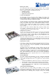
2.5.4 Switching architecture
The M20/M40/M160 switch architecture is based on a shared memory fabric that
uses highly integrated ASICs to handle and forward packets as efficiently as
possible. The switch fabric is referred to as the Packet Forwarding Engine (PFE).
The PICs, FPCs, Backplane and System Control Board (SCB) form the PFE and
each plays an active role in packet forwarding.
The PFE consists of a set of Juniper-developed custom ASICs. The
M20/M40/M160 PFE consists of a single-stage, shared memory system with a
central 40 Mpps ASIC lookup engine. Packets are written to and read from
memory only once, ensuring more efficient throughput. Packet memory is
located on Flexible PIC Controller (FPC) cards so that as interfaces are added,
the required memory is also added. Single-stage buffering greatly reduces
complexities and throughput delays associated with multistage buffering systems.
The shared memory advantages are efficient utilization of buffer memory, no
head of line blocking, and a natural fit to multicast applications.
All paths between the ASICs in the PFE are oversized, dedicated channels.
Memory bandwidth and lookups are considerably oversized and the shared
memory approach eliminates the head of line blocking challenges of a crossbar
system. This is evidenced by the fact that the M40/M20 can handle sustained
bursts of minimum sized packets without packet loss.
The packet forwarding engine architecture for the M40 is explained below. The
M20 and M160 have the same architecture as the M40. For the description of the
switching architecture, the M40 is used as an example but the same
characteristics apply to the M20 and M160.
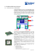
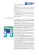
The function of the packet forwarding engine can be understood by following
the progress of a packet into a line card (FPC), through the switching fabric, and
then out of another line card for transmission to the next network element.
Packets arrive into the M20/M40/M160 system via a PIC interface on a FPC card.
Each packet is received and parsed by the media-specific ASIC on the PIC, and
then forwarded to the I/O Manager ASIC on the FPC. The I/O Manager ASIC
parses the Layer 2 headers, and examines the IP header length, time-to-live byte,
and IP header checksum before chopping the packets into 64-byte cells. These
cells are sized appropriately for efficient storage and retrieval from pooled
memory, and are unrelated to ATM cells.
The Distributed Buffer Manager (incoming) ASIC, directs the temporary storage
of the cells into a pooled memory (packet memory) provided collectively by all
available FPCs. The packet memory is considered as a single bank of memory
and is managed as a single resource by the Distributed Buffer Manager ASICs,
although it is actually located on each individual FPC. The Distributed Buffer
Manager (incoming) ASIC ensures an even distribution of cells across all FPCs.
The Distributed Buffer Manager (incoming) ASIC transmits the packet header
information gathered by the I/O Manager ASIC to the Internet Processor ASIC,
where a forwarding decision is made. The results of this decision are transmitted
to the relevant outgoing interface, and Distributed Buffer Manager (outgoing)
ASIC receives the relevant cells back from the pooled memory.
Distributed
Buffer
Manager
ASIC
Distributed
Buffer
Manager
ASIC
Internet
Processor II
ASIC
Shared Memory
PIC
I/O
card
I/O
Manager
ASIC
PIC
I/O
card
I/O
Manager
ASIC
Forwarding
Table
Routing
Table
Forwarding
Table