
Specifications


Page 34 /148
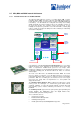
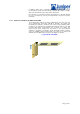
The Connector Interface Panel (CIP) is located at the left side of the FPC card
cage. The CIP consists of connectors for the Routing Engines, Building
Integrated Timing Source (BITS) interfaces for the MCS, and alarm relay
contacts.
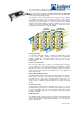
Routing Engine Ports
The CIP has two sets of ports for connecting the Routing Engines to external
management devices. You can use the command-line interface on these
management devices to configure the router.
The upper set of ports, marked HOST0, connects to the Routing Engine in the
RE0 slot, and the lower set, marked HOST1, connects to the Routing Engine in
the RE1 slot. Each set includes the following ports :
§ Console port—Used to connect a system console to a Routing Engine
with an RS-232 serial cable.
§ Auxiliary port—Used to connect a laptop or modem to a Routing Engine
with an RS-232 serial cable.
§ Ethernet management port—Used to connect a Routing Engine to a
management LAN (or any other device that plugs into an Ethernet
connection) for out-of-band management of the router. The Ethernet port
can be 10 or 100 Mbps and uses an autosensing RJ-45 connector.
The Ethernet management port has two LEDs, which indicate the type of
connection in use. A yellow LED lights when a 10-Mbps connection is in use, and
a green LED lights when a 100-Mbps connection is in use.
BITS Interfaces
The CIP has a pair of Building Integrated Timing Source (BITS) interfaces for
connecting the router to external clock sources. The BITS A interface connects to
HOST0 and the BITS B interface connects to HOST1. These interfaces are
located below the Routing Engine management ports.
Alarm Relay Contacts
The CIP has two sets of relay contacts for connecting the router to external alarm
devices. Whenever a system condition triggers either the red or yellow alarm on
the craft interface, the alarm relay contacts also are activated. The alarm relay
contacts are located below the BITS interfaces.
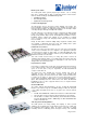
Power Supplies
The router has two load-sharing DC power supplies. The power supplies are
located at the lower rear of the chassis, below the rear lower impeller and the
circuit breaker box. The power supplies are internally connected to the midplane,
which delivers the power input from the circuit breaker box and distributes the
different output voltages produced by the power supplies to the router’s
components, depending on their voltage requirements.
The power supplies are fully redundant. If one power supply fails or is removed,
the second power supply instantly assumes the entire electrical load. A single
power supply can provide full power (up to 2600 W) for as long as the system is
operational. Redundancy is necessary only in case of power supply failure.
The router supports DC power supplies only. Power supplies are hot-removable
and hot-insertable. Each power supply has handles to facilitate removal from the
chassis.
The power supplies are cooled by air drawn through the chassis by the cooling
system components.
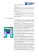
Power Supply LEDs
Four LEDs on each power supply faceplate indicate the power supply’s status. In
addition, a fail condition triggers the red alarm LED on the craft interface.
Power Supply Self-Test Button
Below the power supply LEDs is a self-test button that is used to test the power
supply. Only qualified service personnel should use the self-test button.
Cooling System
The router’s cooling system consists of two separate subsystems: